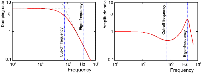
A damping ratio is often applied for harmonic analysis. In practice this approach only leads to satisfying results if all frequency steps can be represented by the same damping ratio or the operating range encloses just one eigenmode. Difficulties arise if the damping ratio depends strongly on the excitation frequency as happens in case of viscous damping in gaseous environment.
A typical damping ratio verse frequency function is shown below. For this example, the damping ratio is almost constant below the cut-off frequency. Harmonic oscillations at frequencies below cutoff are strongly damped. Above cut-off the damping ratio decreases. Close to the structural eigenfrequency the damping ratio dropped down to about 0.25 and a clear resonance peak can be observed.
Damping and stiffness coefficients in modal coordinates are defined based on their nodal coordinate values as:
(14–153) |
and
(14–154) |
where:
| [C] = damping coefficient in modal coordinates |
|
|
| {ϕi} = eigenvector i (in modal coordinates) |
| [C*] = finite element damping matrix in modal coordinates |
| [K*] = finite element stiffness matrix in nodal coordinates |
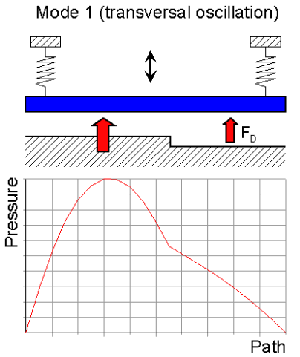
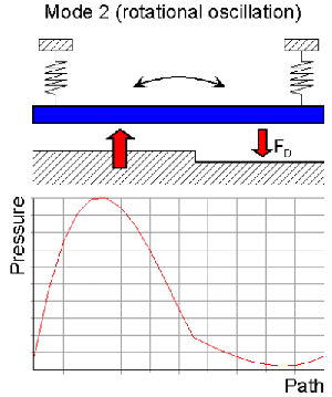
Unfortunately, both matrices [C*] and [K*] are not directly available for the fluid part of the coupled domain problem (e.g., squeeze film elements FLUID136). Moreover eigenvectors are derived from the structural part of the coupled domain problem and consequently neither the modal damping matrix nor the modal stiffness matrix of the fluidic system are necessarily orthogonal. Essential off-diagonal elements occur in case of asymmetric film arrangements or asymmetric plate motion as shown below.
The goal is to express the viscous damping in modal coordinates as follows:
(14–155) |
where:
| {F} = modal force vector |
| {q} = vector of modal displacement amplitudes |
|
|
| [C] = unknown modal damping matrix |
| [K] = unknown modal squeeze stiffness matrix |
The following algorithm is necessary to compute all coefficients of the modal damping and stiffness matrix:
Start with the first mode and excite the fluid elements by wall velocities which correspond to a unit modal velocity. In fact the nodal velocities become equal to the eigenvector of the appropriate mode.
Compute the real and imaginary part of the pressure distribution in a harmonic analyses.
Compute modal forces with regard to all other modes. The ith modal force states how much the pressure distribution of the first mode really acts on the ith mode.
The computed modal forces can be used to extract all damping and squeeze stiffness coefficients of the first column in the [C] and [K] matrices.
Repeat step 1 with the next eigenvector and compute the next column of [C] and [K].
The theoretical background is given by the following equations. Each coefficient Cji and Kji is defined by:
(14–156) |
and
(14–157) |
where:
| F(qi) = complex nodal damping force vector caused by a unit modal velocity of the source mode i. |
|
|
Note that the modal forces are complex numbers with a real and imaginary part. The real part, Re, represents the damping force and the imaginary part, Im, the squeeze force, which is cause by the fluid compression. The damping and squeeze coefficients are output by DMPEXT and are given by:
(14–158) |
and
(14–159) |
Assuming the structure is excited by a unit modal velocity we obtain:
(14–160) |
and
(14–161) |
where:
| Ω = excitation frequency (input on DMPEXT command) |
Modal damping ratios ξ or the squeeze stiffness to structural stiffness ratio KRatio are defined only for the main diagonal elements and are also output with the DMPEXT command. These numbers are computed by:
(14–162) |
and
(14–163) |
where:
| mi = modal mass and the eigenfrequency ωi |
The damping ratio is necessary to compute α and β (input as ALPHAD and BETAD commands) parameters for Rayleigh damping models or to specify constant or modal damping (input by DMPRAT or MDAMP commands).
The squeeze to stiffness ratio specifies how much the structural stiffness is affected by the squeeze film. It can not directly be applied to structural elements but is helpful for user defined reduced order models.


