


The analysis uses an automatic time-stepping scheme, performing approximately 35 substeps in the first load step and approximately 202 substeps in the second load step. (The exact number of substeps is subject to change depending on the hardware platform used to run the analysis.)
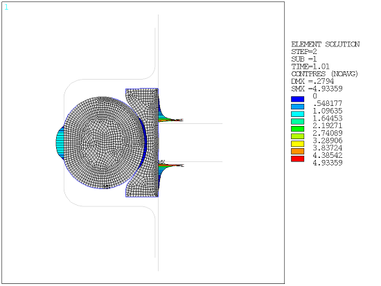
The deformed configuration and the contour of the contact pressures on the seals at the end of the first load step are shown in the following figure:
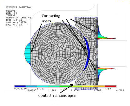
Contact occurs in several areas, as follows:
The middle part of the contact interface between the o-ring and the shaft
The middle part of the contact interface between the o-ring and the cap
The top and bottom part of the contact interface between the cap and the groove.
The top and bottom part of contact interfaces between the seals and the shaft remains open.
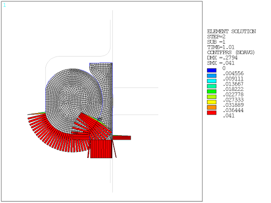
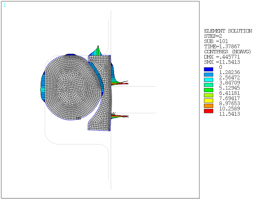
The fluid penetration pressure loads are applied during the second load step. The fluid pressure is active immediately on elements near the bottom part of contact interfaces where the contact status is open.
The fluid pressure does not spread to the elements around the top part of the seals because gaps have been closed near the middle part of the interfaces.
The propagation of the fluid penetration is captured in the following figures showing the deformed shape, the fluid pressure contour, and the contact pressure contour corresponding to different stages of the applied loading. The fluid pressures applied to the surfaces range from 0.041 MPa in the first substep to 4.1 MPa in the last substep.
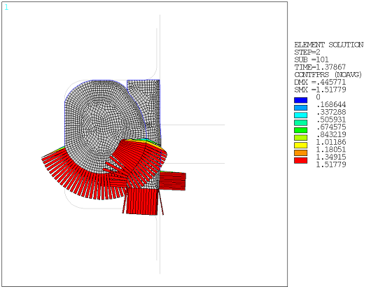
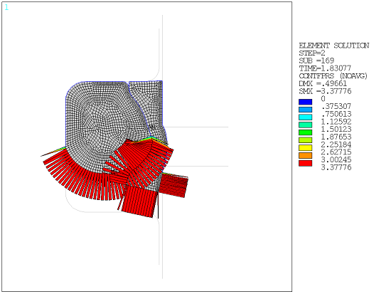
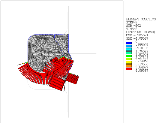

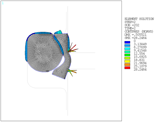
Increasing pressure penetration loads applied in the second load step force the o-ring and cap to be pushed up against the shaft, eventually causing complete contact between the seals and upper part of the shaft. Throughout the loading history, there is no evidence of complete fluid penetration as the contact in certain regions remains closed.
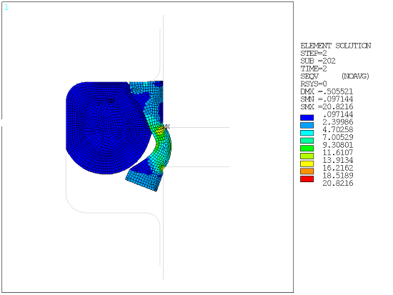
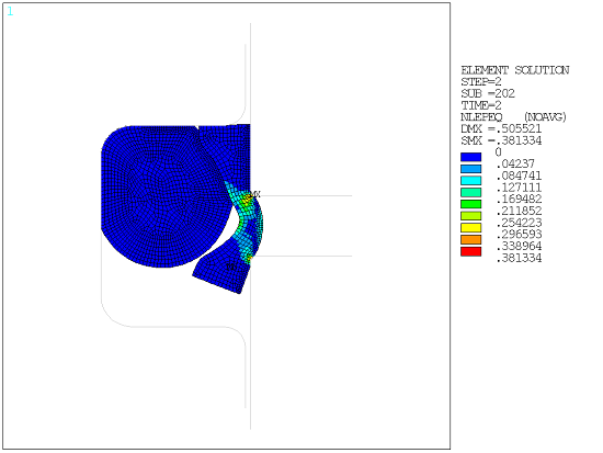
The analysis also shows a certain degree of extrusion of the plastic cap through the extrusion gap of the groove near the end of the second load step. Because the plastic cap is softer than the o-ring, deformations and stresses in the cap are higher than those in the o-ring.
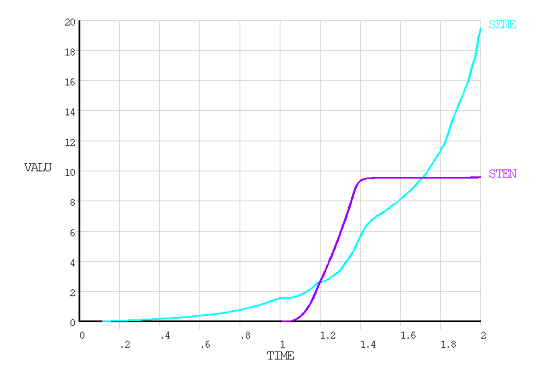
In the early stages of loading (TIME < 1.27), slight strain energy (SENE) is developed and the seals are pushed up almost rigidly. The stabilization energy (STEN) is developed to prevent rigid body motion; without stabilization, the solution diverges.
In the later stage of the loading (TIME > 1.27), the seals deform as the result of compression and strain energy is developed while the stabilization energy remains constant. Eventually, the stabilization energy is less than the strain energy by a factor of three. The stabilization feature helps to prevent potential rigid body motion and improves the convergence while having little effect on the final results.