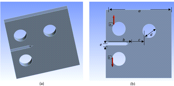
The following model with local stress concentrations is the subject of this analysis:
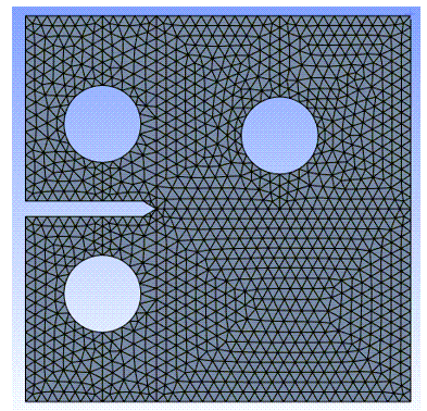
The specimen is meshed with SOLID187 elements:
A finer mesh is not required around the crack front, as the program adjusts the mesh size automatically (via mesh refinement during the first step in the crack-growth and remeshing process).
During the simulation, the edge crack in the CT specimen grows, then merges to the hole. The cutting-through on the hole causes stress redistribution in the model, and a high-stress concentration zone appears at the opposite side of the hole.
Eventually, the stress exceeds the critical stress of material and initializes a crack. In this example, the maximum principal stress is used as an indicator of crack initialization. A new crack is generated automatically at the risk zone and propagates toward the right boundary.


