The following input listing shows the model setup, including node and element definitions, material definitions, and section definitions. This PREP7 input was used for all the examples in this discussion.
Beam Model Setup
/BATCH,LIST
/PREP7
!Parameters
PI=3.1415926536

!Element type definitions
ET,1,188		!Beam element

!Node definitions
N,1,0.,0.,0.
N,2,0.,0.,0.6

!Material properties
MP,EX,1,2.01E11	!Young's modulus for Steel
MP,NUXY,1,0.3	!Poisson's ratio

!Section properties
SECTYPE,1,BEAM,RECT
SECDATA,0.1,0.2	!Beam cross-section

!Element definitions
TYPE,1
MAT,1
REAL,1
SECNUM,1
EN,1,1,2

FINISH
The following input illustrates compound rotations imposed over multiple load steps with each component applied sequentially on top of the previous deformed configuration.
Example 1: Sequentially Applied Rotations
/prep7
!parameters
pi=3.1415926536

!element type definitions
et,1,188		!beam element

!node definitions
n,1,0.,0.,0.
n,2,0.,0.,0.6

!material properties
mp,ex,1,2.01e11	!young's modulus for steel
mp,nuxy,1,0.3	!poisson's ratio

!section properties
sectype,1,beam,rect
secdata,0.1,0.2	!beam cross-section

!element definitions
type,1
mat,1
real,1
secnum,1
en,1,1,2

finish

/solu			!solution
nlgeom,on		!geometrically nonlinear analysis

!boundary conditions for load step 1
d,1,ux,0.0		!displacement at node 1 fixed in x-direction
d,1,uy,0.0		!displacement at node 1 fixed in x-direction
d,1,uz,0.0		!displacement at node 1 fixed in x-direction
d,1,rotx,-pi/6.0	!60° clockwise rotation at node 1 about x-direction
d,1,roty,0.0		!rotation at node 1 fixed about y-direction
d,1,rotz,0.0		!rotation at node 1 fixed about z-direction
time,1.0		!time at the end of load step 1
nsub,10,100,10	!initial, maximum and minimum number of substeps
outres,all,all	!save results
solve		!solve load step 1

!boundary conditions for load step 2
!60° clockwise rotation at node 1 about x-axis (from load step 1)
d,1,rotx,-pi/6.0
!y-component of 90° counterclockwise rotation at node 1 about local z-axis
d,1,roty,(pi/2.0)*sin(pi/6.0)
!z-component of 90° counterclockwise rotation at node 1 about local z-axis
d,1,rotz,(pi/2.0)*cos(pi/6.0)
time,2.0		! time at the end of load step 2
nsub,10,100,10
outres,all,all
solve		!solve load step 2

!boundary conditions for load step 3
!60° clockwise rotation at node 1 about x-axis (from load step 1)
d,1,rotx,-pi/6.0
!y-component of 90° counterclockwise rotation at node 1 about local z-axis (from load step 2)
!and y-component of 90° counterclockwise rotation at node 1 about local x-axis
d,1,roty,(pi/2.0)*sin(pi/6.0)+(pi/2.0)*cos(pi/6.0)
!z-component of 90° counterclockwise rotation at node 1 about local z-axis (from load step 2)
!and z-component of 90° counterclockwise rotation at node 1 about local x-axis
d,1,rotz,(pi/2.0)*cos(pi/6.0)-(pi/2.0)*sin(pi/6.0)
time,3.0		! time at the end of load step 3
nsub,10,100,10
outres,all,all
solve		!solve load step 3
finish

/post26		!time-history postprocessor
nsol,2,1,rot,x,rotx1	!store results for rotation about x-axis at node 1
nsol,3,1,rot,y,roty1	!store results for rotation about y-axis at node 1
nsol,4,1,rot,z,rotz1	!store results for rotation about z-axis at node 1
nsol,5,2,u,x,ux2		!store results for x-displacement at node 2
nsol,6,2,u,y,uy2		!store results for y-displacement at node 2
nsol,7,2,u,z,uz2		!store results for z-displacement at node 2
prvar,2,3,4			!print results
prvar,5,6,7
finish
The following input illustrates compound rotational velocities imposed over multiple load steps with each component applied sequentially. The difference between imposing rotations and rotational velocities should be noted.
Example 2: Sequentially Applied Rotational Velocities
/prep7
!parameters
pi=3.1415926536

!element type definitions
et,1,188		!beam element

!node definitions
n,1,0.,0.,0.
n,2,0.,0.,0.6

!material properties
mp,ex,1,2.01e11	!young's modulus for steel
mp,nuxy,1,0.3	!poisson's ratio

!section properties
sectype,1,beam,rect
secdata,0.1,0.2	!beam cross-section

!element definitions
type,1
mat,1
real,1
secnum,1
en,1,1,2

finish

/solu			!solution
nlgeom,on		!geometrically nonlinear analysis
kbc,1    		!step applied load/boundary condition

!boundary conditions for load step 1
d,1,ux,0.0		!displacement at node 1 fixed in x-direction
d,1,uy,0.0		!displacement at node 1 fixed in x-direction
d,1,uz,0.0		!displacement at node 1 fixed in x-direction
d,1,omgx,-pi/6.0	!60°/s clockwise rotational velocity at node 1 about x-direction
d,1,omgy,0.0	!zero rotational velocity at node 1 about y-direction
d,1,omgz,0.0	!zero rotational velocity at node 1 about z-direction
time,1.0		!time at the end of load step 1
nsub,10,100,10	!initial, maximum and minimum number of substeps
outres,all,all	!save results
solve		!solve load step 1

!boundary conditions for load step 2
!zero rotational velocity at node 1 about x-direction
d,1,omgx,0.0
!y-component of 90°/s counterclockwise rotational velocity at node 1 about local z-axis
d,1,omgy,(pi/2.0)*sin(pi/6.0)
!z-component of 90°/s counterclockwise rotational velocity at node 1 about local z-axis
d,1,omgz,(pi/2.0)*cos(pi/6.0)
time,2.0		! time at the end of load step 2
nsub,10,100,10
outres,all,all
solve		!solve load step 2

!boundary conditions for load step 3
 !zero rotational velocity at node 1 about x-direction
d,1,omgx,0.0
!y-component of 90°/s counterclockwise rotational velocity at node 1 about local x-axis
d,1,omgy,(pi/2.0)*cos(pi/6.0)
!z-component of 90°/s counterclockwise rotational velocity at node 1 about local x-axis
d,1,omgz,-(pi/2.0)*sin(pi/6.0)
time,3.0		! time at the end of load step 3
nsub,10,100,10
outres,all,all
solve		!solve load step 3
finish

/post26		!time-history postprocessor
nsol,2,1,rot,x,rotx1	!store results for rotation about x-axis at node 1
nsol,3,1,rot,y,roty1	!store results for rotation about y-axis at node 1
nsol,4,1,rot,z,rotz1	!store results for rotation about z-axis at node 1
nsol,5,2,u,x,ux2		!store results for x-displacement at node 2
nsol,6,2,u,y,uy2		!store results for y-displacement at node 2
nsol,7,2,u,z,uz2		!store results for z-displacement at node 2
prvar,2,3,4			!print results
prvar,5,6,7
finish
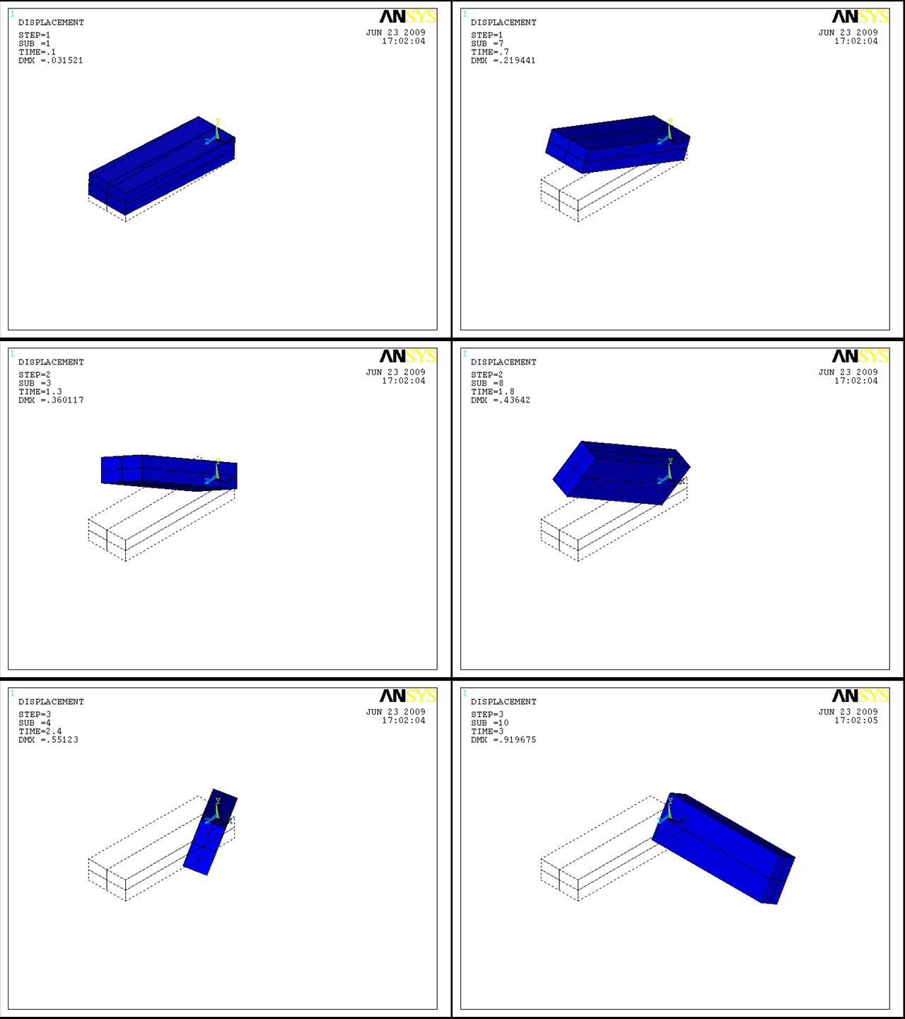
The following animation shows how the beam deforms under the sequentially applied load. The result is the same for applied rotations and applied rotational velocities.
The following input illustrates compound rotations imposed over a single load step with all components applied together.
Example 3: Simultaneously Applied Rotations
/prep7
!parameters
pi=3.1415926536

!element type definitions
et,1,188		!beam element

!node definitions
n,1,0.,0.,0.
n,2,0.,0.,0.6

!material properties
mp,ex,1,2.01e11	!young's modulus for steel
mp,nuxy,1,0.3	!poisson's ratio

!section properties
sectype,1,beam,rect
secdata,0.1,0.2	!beam cross-section

!element definitions
type,1
mat,1
real,1
secnum,1
en,1,1,2

finish

/solu			!solution
nlgeom,on		!geometrically nonlinear analysis

!boundary conditions for load step 1
d,1,ux,0.0		!displacement at node 1 fixed in x-direction
d,1,uy,0.0		!displacement at node 1 fixed in x-direction
d,1,uz,0.0		!displacement at node 1 fixed in x-direction
!60° clockwise rotation at node 1 about x-axis
d,1,rotx,-pi/6.0
!y-component of 90° counterclockwise rotation at node 1 about local z-axis
!and y-component of 90° counterclockwise rotation at node 1 about local x-axis
d,1,roty,(pi/2.0)*sin(pi/6.0)+(pi/2.0)*cos(pi/6.0)
!z-component of 90° counterclockwise rotation at node 1 about local z-axis
!and z-component of 90° counterclockwise rotation at node 1 about local x-axis
d,1,rotz,(pi/2.0)*cos(pi/6.0)-(pi/2.0)*sin(pi/6.0)
time,1.0		!time at the end of load step 1
nsub,30,100,30	!initial, maximum and minimum number of substeps
outres,all,all	!save results
solve		!solve load step 1
finish

/post26		!time-history postprocessor
nsol,2,1,rot,x,rotx1	!store results for rotation about x-axis at node 1
nsol,3,1,rot,y,roty1	!store results for rotation about y-axis at node 1
nsol,4,1,rot,z,rotz1	!store results for rotation about z-axis at node 1
nsol,5,2,u,x,ux2		!store results for x-displacement at node 2
nsol,6,2,u,y,uy2		!store results for y-displacement at node 2
nsol,7,2,u,z,uz2		!store results for z-displacement at node 2
prvar,2,3,4			!print results
prvar,5,6,7
finish
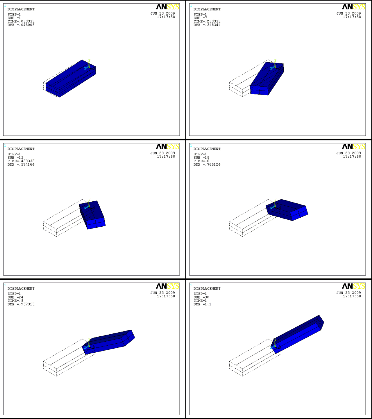
The following animation shows how the beam deforms under the simultaneously applied load.


