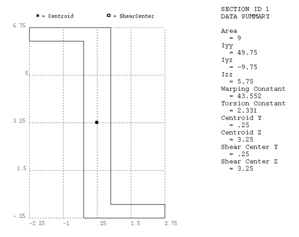
A cross section defines the geometry of the beam or pipe in a plane perpendicular to
the beam axial direction. A library of eleven commonly-used cross section shapes is
available, and user-defined shapes are available. When a cross section is defined, the
program builds a numeric model using a nine node cell for determining the properties
(Iyy, Izz, etc.) of the
section and for the solution to the Poisson's equation for torsional behavior.
Figure 12.1: Plot of a Z Cross Section shows the centroid and shear center of the cross section and the calculated section properties:
Cross sections and user section meshes may be saved and stored in cross section library files. You may assign beam cross sections as attributes of a line using the LATT command. These section definitions will be incorporated into the generated beam elements when the line is meshed with BEAM188, BEAM189, or ELBOW290.


