Overconstraint means that more constraints than necessary have been applied to the degrees of freedom at a node.
For example, the following conditions can result in overconstraints:
Overconstraints may arise when rigid bodies are joined together using multiple joint elements. The overconstraints can occur due to redundant joints performing the same function or contradictory motion resulting from improper use of joints connecting different bodies.
The following examples illustrate scenarios in which overconstraint conditions can occur.
In this scenario, all components are rigid. The example shows how overconstraint can occur even in simple models.
Consider the standard 3D four-bar mechanism shown here. (See Geradin and Cardona in Learning More About Multibody Dynamics.) The mechanism consists of four rigid links and four revolute joints.
Solution: Replace three of the revolute joints with spherical joints.
With six degrees of freedom available for each rigid body, the four rigid bodies yield a total of 6 * 4 = 24 degrees of freedom. A revolute joint has only one free degree of freedom and five constraints. Thus, the four revolute joints impose a total of 5 * 4 = 20 constraints. If one of the rigid links is fixed in space, then an additional six constraints are imposed. If a rotation is applied at one of the revolute joints (thereby adding one more constraint), the number of overconstraints is 24 - (20 + 6 + 1) = -3. As modeled, therefore, this mechanism is overconstrained.
In such a case, you can resolve the overconstraints by replacing three of the revolute joints with spherical joints. Each spherical joint imposes only three constraints; after replacing the joint type, a degree-of-freedom count indicates that the system is no longer overconstrained. While the overconstraint in this model can be resolved fairly easily, this is not a typical case. It is therefore vital that you exercise care when setting up your model. For more information, see Resolving Overconstraint Problems.
This simple example illustrates overconstraints caused by redundant rigid components.
The figure shows a plate modeled with shell elements. A portion of the plate is made rigid by adding MPC184 Rigid Beam elements (represented by the thick lines in the figure). The addition of rigid beams AB and BC is redundant and leads to an overconstrained model.
In Mechanical APDL, if the MPC184 Rigid Beam elements with direct elimination option are used to model this type of problem, the redundant constraints are eliminated automatically. However, if MPC184 Rigid Beam with the Lagrange multiplier option is used, the solution may not converge.
Redundant boundary conditions can lead to overconstraint. In some cases, the multibody mechanism may actually end up as a "structure" with zero mobility if improper boundary conditions are applied.
In some cases involving MPC184 Rigid Beam elements with the direct elimination option (which is based on all degrees of freedom at a node), redundant boundary conditions can result in an overconstrained system.
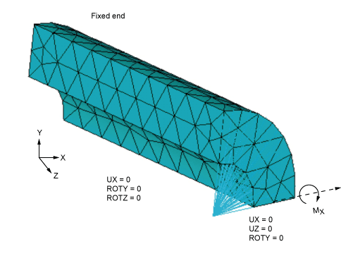
Consider a cylindrical tube with one end fixed and subjected to a bending moment at the other end. A quarter of the cylinder is modeled with appropriate symmetry and antisymmetry boundary conditions as shown in the following figure. MPC184 Rigid Beam elements with the direct elimination option connect all the nodes of the tube to a center point, and a moment is applied at the center node.
Because of the symmetry and antisymmetry boundary conditions, the system of internal constraint equations generated due to the MPC184 Rigid Beam element results in an overconstrained system.
User-defined constraint equations (created via the CE and CP commands) can conflict with the internal constraint equations generated for the rigid bodies using the contact MPC capability or the joint elements. Ansys, Inc. recommends avoiding user-defined CEs and/or CPs while performing a flexible multibody simulation.


