The master degrees of freedom are the degrees of freedom of the superelement which you intend to use to connect to the degrees of freedom of the remaining bodies and joints. Because you almost always use all degrees of freedom of a node in the definition of the master degrees of freedom, you can think in terms of master "nodes"; that is, the master degrees of freedom are the nodes of the superelement that connect to the nodes of the remaining joints and bodies.
If the connection occurs at a joint at the center of a hole or slot, you must place a master node there. For more information, see Connecting Bodies to Joints.
Nonrotating Bodies
For nonrotating bodies, master nodes are located at the points where the superelement connects with the other bodies and are typically located at the centers of bolts or other fasteners and bearings. Try to minimize the number of master nodes. Where appropriate, use the techniques presented in Connecting Bodies to Joints to create a single master node that connects to a number of nodes.
Rotating Bodies
For rotating bodies, the idea is to create a beam-like superelement, ideally with two master nodes (but never less than two). You can use more than two master nodes (for example, when modeling a lever or rocker plate), but Mechanical APDL assumes that the rotation of the superelement is the average of the rotations of all master nodes.
All master nodes of a rotating body must have six active structural degrees of freedom: UX, UY, UZ, ROTX, ROTY, and ROTZ. If the master node does not have six degrees of freedom--for example, if it is the node of a 3D solid element--create a six-degree-of-freedom node at that location and tie it to the rest of the body appropriately. You can use either of the following techniques, both of which essentially place a six-degree-of-freedom node connected to a patch of elements superimposed on the existing solid elements.
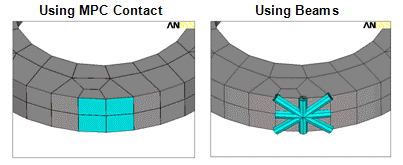
MPC Contact -- Create a pilot node and link it to bonded contact elements overlaid on the patch. For more information, see Connecting Bodies to Joints.
Beams -- Overlay beam elements or MPC184 Rigid Beam elements in a spiderweb fashion. The beams should have high stiffness and no mass.
Following is an illustration of both methods:

When rotating the created node, the body rotates accordingly.
You can also define master degrees of freedom where loads are to be applied as well as at any points where velocities or accelerations are of interest.


