


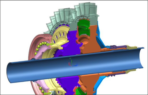
Multistage cyclic symmetry is useful for modeling a physical system with some cyclically symmetric parts. The term multistage comes from the combination of multiple turbomachinery stages as illustrated in Figure 1.1: Turbomachinery Multistage Cyclic Structure. However, it is not limited to turbomachinery analyses. In this guide, a stage refers to a distinct cyclically symmetric structure.
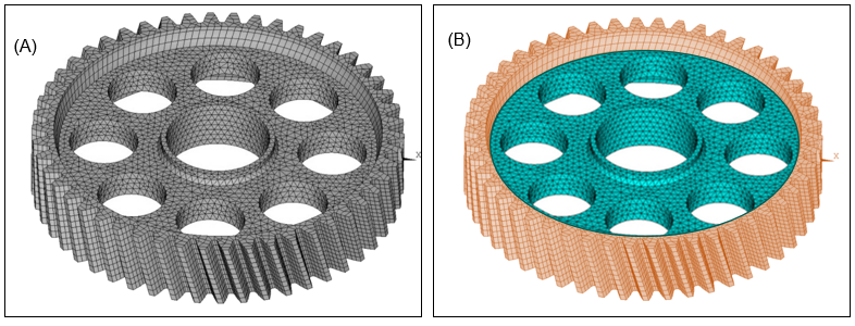
With growing model complexity and fidelity, some details of a single stage system can break the cyclic symmetry. Traditionally, this would require either solving the full 360° model or removing features from the model until it is cyclically symmetric. These model complexities can now be solved using multistage cyclic symmetry. An example would be a single gear having a different number of teeth and stress relief holes as shown in Figure 1.2: Gear (A) Modeled as a Multistage Cyclic Structure with Two Stages (B). The gear (gray) can be modeled using one stage for the hub with stress relief holes (blue) and one stage with the rim and gear teeth (orange).
Systems such as a turbomachinery compressors that have cyclically symmetric stators and blade rows with different sector counts can also be modeled. Within each traditional stage, there may be multiple stages as described above to account for bolt patterns, stress relief holes, blades, and so on.