


Inverse planar plate experiments are used to obtain the uniaxial compression behavior at strain rates up to 104/s. This method is very well adapted to characterize the shock compression behavior of unknown materials. Studies have shown the importance of equation of state properties for accurate simulations of composite materials subjected to hypervelocity impact [1].
A schematic of the test is given in Figure 5.6: Configuration of Inverse Planar Impact Experiments and a Typical Velocity Trace from the Rear Surface of the Witness Plate. A projectile consisting of cylindrical samples of the composite being tested, covered typically with an aluminum backing, are accelerated in a gas gun to velocities up to 1000 m/s. The projectile then impacts a stationary witness plate of well characterized steel. The velocity of the rear surface of the witness plate is recorded using a high resolution VISAR laser interferometer.
Figure 5.6: Configuration of Inverse Planar Impact Experiments and a Typical Velocity Trace from the Rear Surface of the Witness Plate
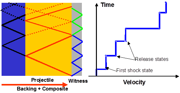
Figure 5.6: Configuration of Inverse Planar Impact Experiments and a Typical Velocity Trace from the Rear Surface of the Witness Plate shows a typical velocity trace for an inverse flyer plate experiment. After shocking the arriving material sample and the stationary witness plate on the contact surface to their respective Hugoniot states, the stress waves travel through both plates. The pressure wave inside the witness plate is converted to a pressure release wave at the free surface and propagates back into the steel. Due to the impedance mismatch between steel and the sample material, this wave is only partially transmitted across the impact surface into the sample. It is mainly converted back to a pressure wave, which provides a further velocity increase when reaching the free surface of the witness plate. The repeated reflection of the wave at the surfaces results in stepwise increase of the free surface velocity.
The complete impact conditions in the sample can be calculated without any assumption on the material’s equation of state. Shock states are determined using the Rankine-Hugoniot equations, and the free surface velocity can be used to obtain the particle velocity, since the measured free surface velocity ufs is approximately equal to twice the particle velocity up of the target at the first shock state of Figure 5.6: Configuration of Inverse Planar Impact Experiments and a Typical Velocity Trace from the Rear Surface of the Witness Plate. Together with the known shock properties of the target, the Rankine Hugoniot equations can be used to deduce all variables of the shock state. Further details of this experiment are given in [1][2].