- 0° Tension Test
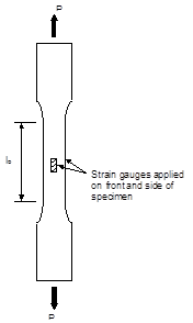
Tensile tests are typically performed to determine the stress-strain response of a composite material in the plane of the laminate. Data commonly generated by this test are the stiffness and strength properties. Samples, of similar shape to that illustrated in Figure 5.1: Schematic Diagram of a Tensile Test Specimen, are cut from the laminate sheets and the ends of the sample are clamped and separated at a constant speed in opposite directions using a machine such as an Instron®. The tension or force required to do this is recorded. The test results are shown as a stress-strain curve, the shape of which provides information about the material behavior of the sample.
Strains can be recorded by using the crosshead displacement of the experimental apparatus, or using an extensometer. Alternatively biaxial strain gauges located both on the side and front of the test specimen allow for measurement of the strains in the principal material directions. In this way both in-plane and through thickness properties can be measured. For unidirectional laminates, samples can be prepared such that the specimens can be orientated either in the direction of the fibers (0° tension test) or at 90° to the fibers (90° tension test).
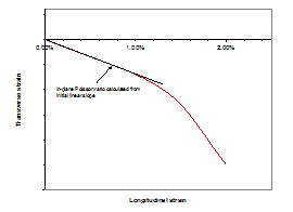
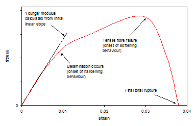
Figure 5.2: Calculation of In Plane and Out of Plane Poisson Ratios and Figure 5.3: Typical Recorded Uniaxial Stress-Strain Relationship show a typical result of a tensile test on a composite material.
- 45° Tension Test
Tension tests on samples manufactured so that the fibers are aligned at 45° orientation to the applied load are performed to derive the in-plane shear modulus according to Equation 5–1 [7]. Instrumentation with longitudinal and transverse strain gauges is applied as in the previous tests of 0° Tension Test.

(5–1)
where EY is the modulus calculated from the initial linear part of the recorded stress-strain relationship which in principal will have similar form to that shown in Figure 5.3: Typical Recorded Uniaxial Stress-Strain Relationship.