


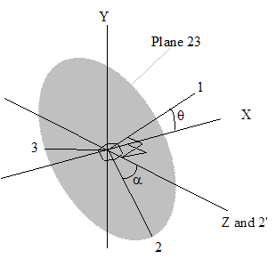
For 3D Lagrange and ALE subgrids, the three principal directions are oriented in XYZ space and are mutually perpendicular. These three directions are defined by the use of four variables as explained below, and illustrated in Figure 2.4: Material directions in Autodyn-3D defined in XYZ-space.
The first principal direction is a vector in XYZ space (1 in Figure 2.4: Material directions in Autodyn-3D defined in XYZ-space) and is defined in Autodyn-3D by the x, y and z components of this vector. The second and third principal directions are two vectors (2 and 3) which lie in a plane that has its normal as the first principal direction. The location of the second and third principal directions are defined in Autodyn-3D by a single angle; this angle (α) is defined as being that between the second principal direction and the vector (2’) which is the cross-product (in other words, is normal to) the X axis and the first principal direction. In Figure 2.4: Material directions in Autodyn-3D defined in XYZ-space, as an example, the direction 1 is shown as vector which is rotated in the XY plane by an angle θ; therefore the direction 2’ is coincident with direction Z. The direction 2 is rotated from 2’ by an angle α in the 23 plane. Note that the principal angle can vary between -90° and +90°. Direction 3 is normal to directions 1 and 2.
You are allowed to define the initial orientation of the principal material axes in one of two ways, as shown below: