A layered composite shell has been implemented in Autodyn-3D. Composite shell elements allow efficient modelling of thin composite materials that are subjected to structural (rather than shock) type loading. All of the existing material models that are compatible with the standard shell element can be applied to individual layers of new composite shell elements. In addition the orthotropic equation of state can be used with the layered composite shell element. The composite shell always assumes that the 11 and 22 directions are in the plane of the shell and the 33 direction lies through the thickness.
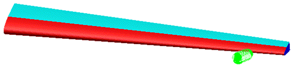
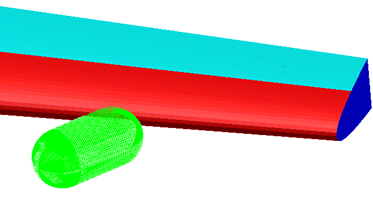
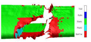
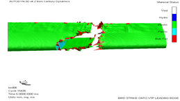
An example composite shell application is shown in Figure 7.12: Initial Configuration of Composite Tail Section to Figure 7.14: Material Status Following Bird Strike. Results from an Autodyn simulation of a bird strike onto the leading edge of a composite tail plane are shown. Figure 7.12: Initial Configuration of Composite Tail Section and Figure 7.13: Initial Configuration of Composite Tail Section: Impact Zone show the initial configuration of the bird and tail section. The bird has been modelled with SPH particles and the tail plane with a combination of composite and standard shell elements. The composite shells have been used to represent the layered GFRP and CFRP skin of the tail section. Figure 7.14: Material Status Following Bird Strike shows material status plots for the tail section following the impact. Results for the outer and inner layers of the skin are shown.