


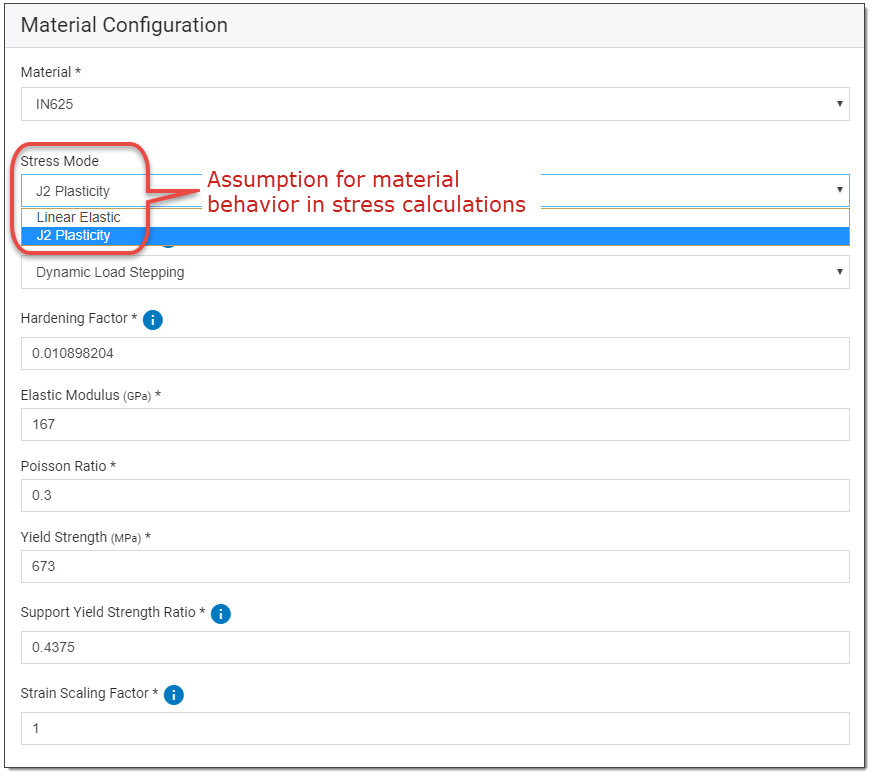
Once you choose a material, you have the option of choosing material behavior in calculations of stress that is either linear elastic or elastoplastic (exhibiting both elastic and plastic properties). The elastoplastic calculations are based upon the J2 (von Mises) plasticity model.
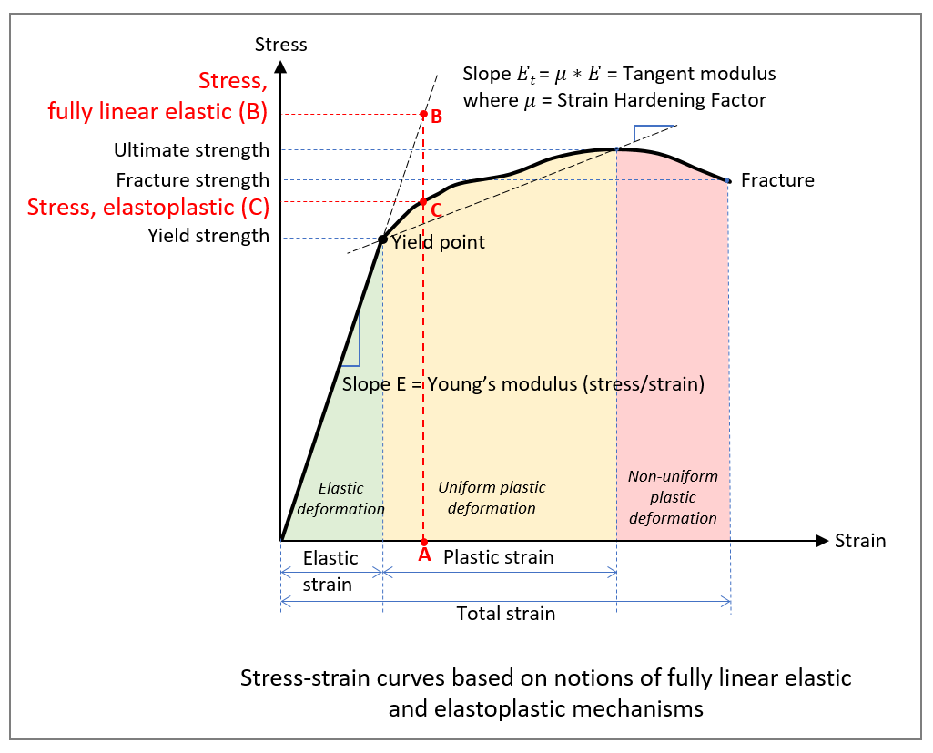
The stress mode option is associated with a material’s ductility, a measure of a material's ability to undergo significant plastic deformation before rupture. The following figure shows stress-strain curves for a typical metal material. After yield, for a given strain, A, in the plastic deformation region, notice that the stress at point B (fully linear elastic) is higher than the stress at point C (elastoplastic). Stress values differ depending on your assumptions about material behavior.
In the Additive application, an assumption of linear elastic behavior will result in higher stress values for a given strain beyond the yield point of the material. This over-prediction may not be realistic for parts with larger strains. The simulation will run faster, however, which may be beneficial if you care about on-plate distortions only (because you will heat-treat the final part to relieve residual stress, for example). It is important to note that while stress values beyond the elastic range will be artificially high, on-plate distortion values will generally be correct using the linear elastic option. Therefore, using linear elastic stress mode can be useful for analyzing distortion trends while the part is still on the baseplate.
An assumption of elastoplastic behavior (using the Bilinear Isotropic HardeningJ2-plasticity model) applies best to ductile materials, such as most metals. Currently, small deformation plasticity has been used in these models where addition of elastic and plastic strains amount to total strain, since metals do not exhibit the large deformations we see in polymers, for example. Von Mises stresses are used to reduce the stress levels when strain values exceed elastic strain. Strain hardening algorithms are included in the stress calculations (see Hardening Factor).
The simulation will run longer with the J2-plasticity option, but this option is required if you want accurate distortion after-cutoff results, or accurate indications of stresses and strains.
Load Stepping Type
If you select the J2-plasticity option, you'll need to specify a Load Stepping Type. To improve convergence, a total load for each layer will be applied in incremental steps in one of the following ways:
Dynamic Load Stepping (default): The full load will be applied initially, and the solver will iterate until equilibrium is achieved. If not achieved with the initial load, it will be halved and repeated. If equilibrium is achieved, the next incremental step is applied at the current load fraction until applying the full load, otherwise, it is halved again. A lower limit of 1/(200) load fraction is enforced, after which the solution will terminate.
Fixed Load Stepping: Fixed load stepping divides the load into a user-defined number of load steps.
Number of Load Steps: The number of increments that a given load will be divided into for plasticity. A larger number of load steps will require more loading calculations, but total time may or may not increase due to potential improvements in convergence. (Valid range is between 1 and 200. Defaults to 8.)
Hardening Factor
If you select the J2-plasticity option, a material-specific strain Hardening Factor is used in stress calculations to provide further information about the material’s behavior in the plastic deformation region. The Hardening Factor is used to calculate the slope of the stress-strain curve (Et) above the material’s Yield stress:

This factor may be changed here or when customizing a material.
Note: Previous to Release 19.2, a hardening factor of 0.1 was used for all materials. Following the 19.2 update, the default materials each have their own hardening factor. Custom materials created by the user prior to this change will use 0.0198 as the hardening factor. A consequence of this change is that simulations run from Release 19.2 forward may have slightly different output values than those run with previous releases. The magnitude of the difference depends on a variety of factors including part geometry and orientation, material, scan pattern, laser power and whether supports are used in the simulation.