Considering the amount of distortion that is possible within a part being built, a scenario of concern is a collision of the recoater blade and the distorted part. The Additive application provides a blade crash detection feature that predicts, based primarily on part distortion, if and where such a collision may occur. Physical blade crash is dependent on other factors, as well, such as scanning procedure, temperatures, gas flows, part orientation, and materials, among others, so it is important to understand that our calculation is a detection of potential blade crash.
On a simulation form under Outputs, check the box for Detect potential blade crash due to distortion. Once selected, you have the option to specify a Threshold Scaling Factor and Layer Thickness. (Note that for Scan Pattern and Thermal Strain simulations, the Layer Thickness parameter appears in the Machine section of the simulation form.)
Once the simulation is complete, a file labeled Potential blade crash locations can be found in the Output Files section under Completed Simulations. Click the export link to get the .csv file. Indications of blade crash are also available on the On-plate stress/displacements .vtk and .avz files and the Layerwise .vtk files.
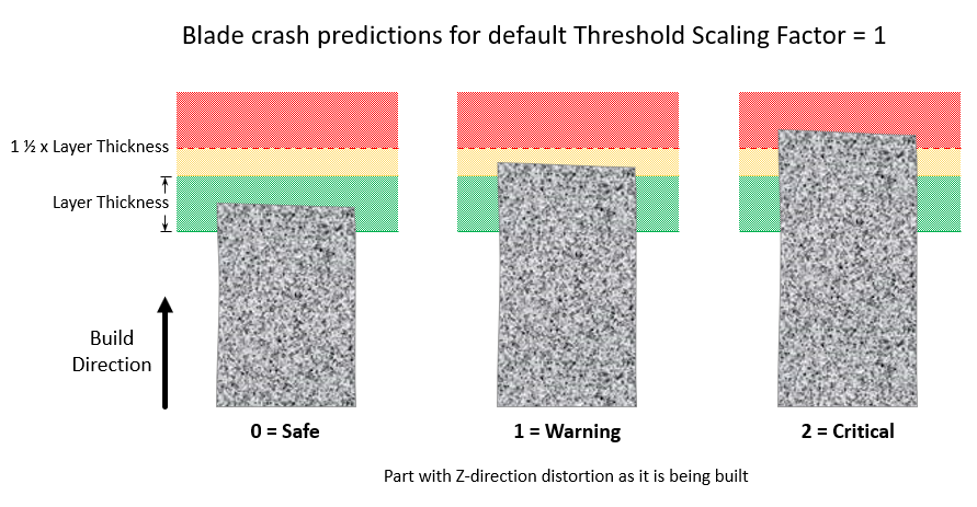
Blade crash potential is calculated and each voxel is assigned a 0, 1, or 2 as follows:
0 (none predicted)
1 = warning/potential blade crash — when positive Z displacement is greater than (Layer Thickness x Threshold).
2 = critical/likely blade crash — when positive Z displacement is greater than (Layer Thickness x Threshold + ½ Layer Thickness). The additional ½ Layer Thickness is an approximation to take into consideration the actual offset distance of the recoater blade needed to deposit a given layer thickness.
Layer Thickness (10-100 μm)
Layer Thickness is the thickness of the powder layer coating that is applied with every pass of the recoater blade. The default value is 50 microns. We recommend that you use the actual thickness specific to your machine.
Threshold Scaling Factor
This value is used to modify blade crash calculations so that you can allow for flexibility in the recoater blade.
Using the default value of 1 and a Layer Thickness value of 50 μm, any displacement in the positive Z direction over 50 μm will be marked as a warning (potential blade crash) and any displacement over 75 μm will be marked as a critical area (likely blade crash). In another example, if you know there is not a lot of flexibility in the recoater blade, use a threshold value of 0.8. With a 50-micron Layer Thickness, any displacement in the positive Z direction over 40 microns will be marked as a warning and any area with displacement greater than 65 microns will be marked as critical.