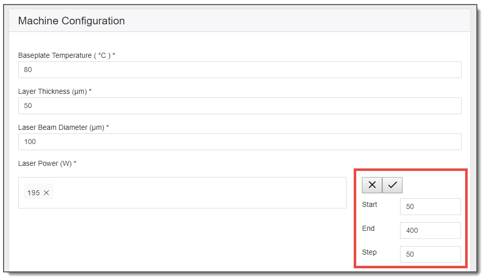
Enter values for the process parameters in this section of the simulation form. Inputs include Baseplate Temperature (°C), Layer Thickness (µm), and Laser Beam Diameter (µm) as constant values and Laser Power (W) and Scan Speed (mm/sec) as parametric variables. You can enter variable values through either the incremental step tool, or manually, or both. (Note that each time you use the incremental step tool it will overwrite the values you have already entered.)
Characteristic Width Calculation Mode
The Use Characteristic Width Calculation Mode check box should be checked only when you are creating user defined materials. When checked, certain parameters are automatically set and are not available for input.
Bead Type
Unique to Single Bead simulations is the input option of Bead Type, an indication of how the bead is deposited. This setting affects the calculation of material state, which in turn affects the material properties used in the solving process, as well as in the laser flux model. You may need to change from the default if you are matching a particular experimental setup.
Bead on powder layer (default): A single bead deposited on top of a layer of powder of Layer Thickness.
Bead on base plate: A single bead deposited directly on solid material.
On-Pad versus On-Plate Layer Thickness
Layer thickness input for a Single Bead simulation should represent the amount of material that is being added to each layer of a build. To compare single bead experiments to the simulation you must make sure that the Layer Thickness input field reflects this. When single bead experiments are deposited on a pad built using the same material and layer thickness as the single bead, that layer thickness is appropriate to use for the simulation. We recommend this technique. By contrast, when single beads are built on a plate that simply has powder spread on top of it, the simulation Layer Thickness must be adjusted based on the powder packing density to account for the consolidation into solid. In this technique, the Layer Thickness should be less than the machine's single bead thickness.
In general, Single Bead simulations show good and consistent data matches with experimental results when the melt pool depths are 2 to 5 times the powder layer thickness. When the melt pool depth is around the powder layer thickness or less, the experimental process is normally unstable (the powder layer is not fully melted and/or balling occurs), and larger differences may occur when comparing simulation results with experimental results.
![]()
Throughout this and the following chapter, we will use an example to demonstrate just one of the many ways you can use Additive Science to gain insights into your PBF process. This is hypothetical example where we have made assumptions about our process goals and chosen material that may not be valid in other cases. We will run a Single Bead Parametric simulation using a generic material.
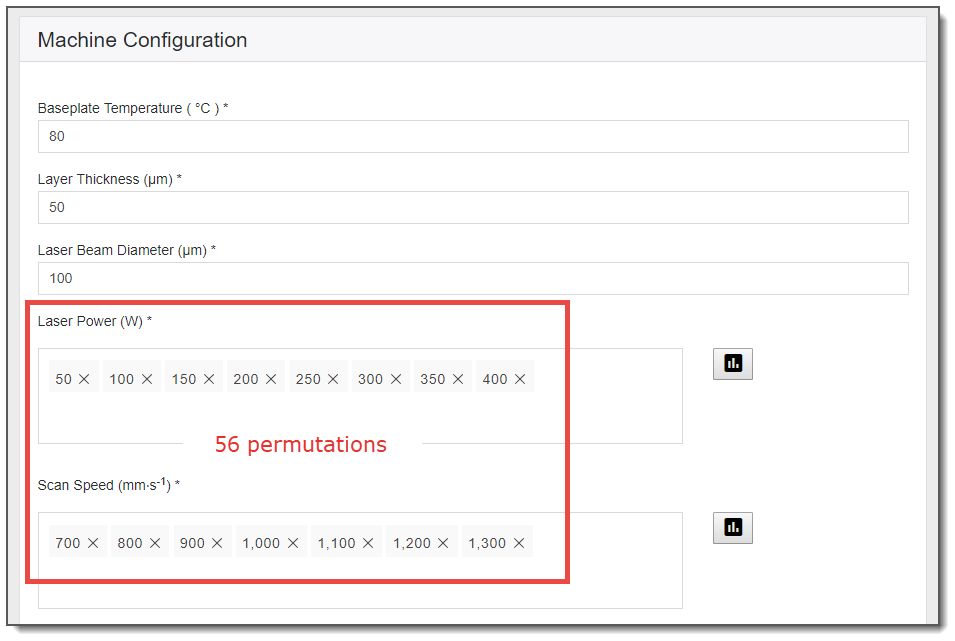
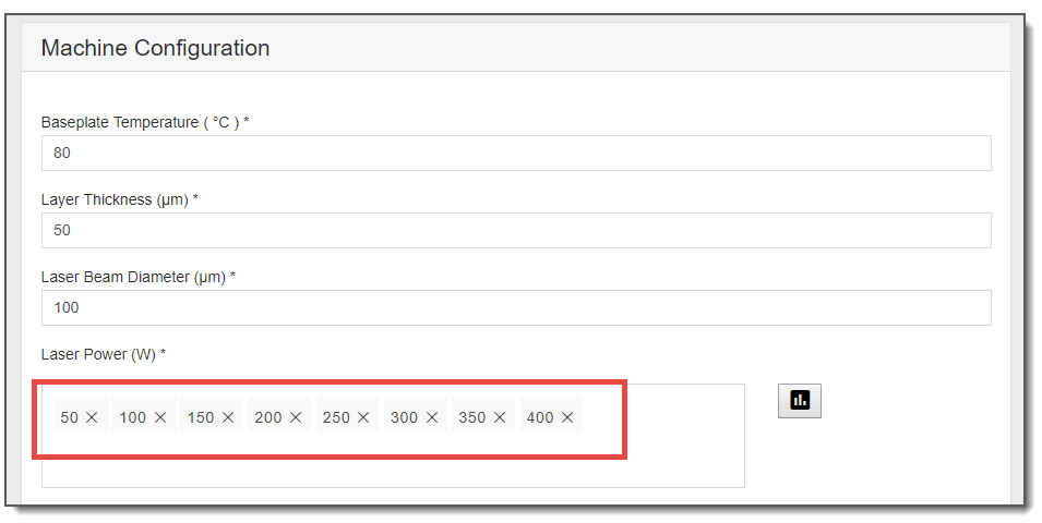
In this example, we entered Laser Powers starting at 50 and ending at 400 in increments of 50. After clicking on the check-mark, the values of 50, 100, 150, 200, 250, 300, 350, and 400 are entered.
Continuing with this example, we entered Scan Speeds between 700 and 1300 in increments of 100. This will result in 56 individual permutations in the simulation. That is, single bead scans will be simulated at a Laser Power of 50 and a Scan Speed of 700, then another one for Laser Power = 50 and Scan Speed = 800, another one at Laser Power = 50 and a Scan Speed = 900, and so on until every combination is performed. This is a full factorial experiment, with each laser power matched with each scan speed. There is a limit of 300 permutations in one simulation.