


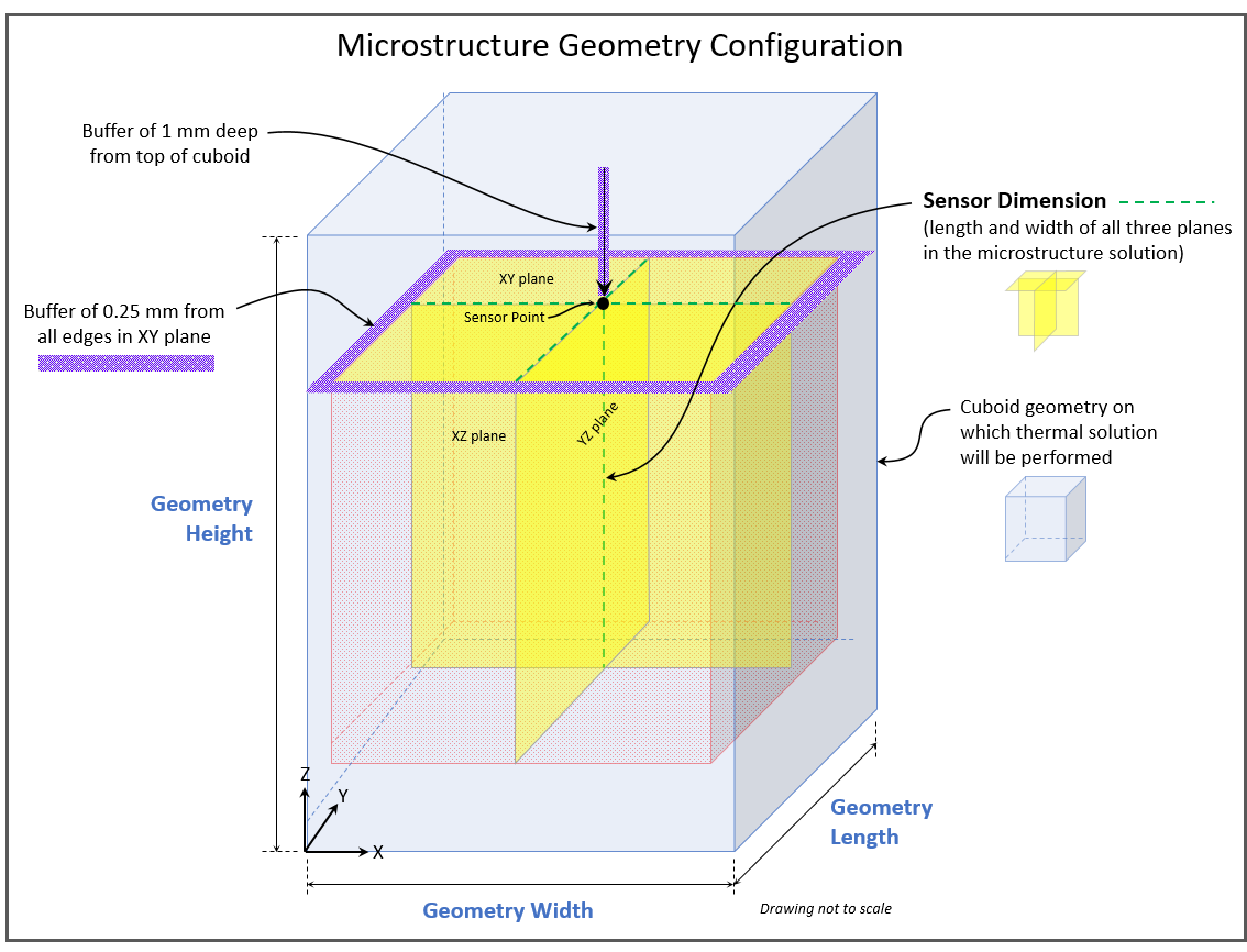
A Microstructure Simulation is essentially a two-part solution. A thermal solution of a cuboid geometry is performed first using the Thermal Solver to determine cooling rate, thermal gradient, and melt pool size (width and depth) for the material given a set of process parameters. Then the Microstructure Solver is used on a smaller "cube" inscribed inside the cuboid to determine the microstructural information. The cube is actually a set of three 2D planes with width and height equal to Sensor Dimension. A 1 mm buffer depth and a 0.25 mm buffer distance from all the edges of the cuboid in the XY plane are required to ensure the microstructure is obtained with a thermal melt pool that has reached steady-state. The thermal quantities of cooling rate, thermal gradient, melt pool width and melt pool depth used by the Microstructure Solver are single, averaged values and are averaged from within the microstructure cube only.
Geometry Configuration
Geometry Width (mm) - The width of the cuboid, in millimeters, for the thermal solution. Geometry Width must be at least Sensor Dimension plus 0.5 mm (for a 0.25 mm buffer on each side). Valid input values are positive real numbers between 1 and 10. Defaults to 1.5 mm.
Geometry Length (mm) - The length of the cuboid, in millimeters, for the thermal solution. Geometry Length must be at least Sensor Dimension plus 0.5 mm (for a 0.25 mm buffer on each side). Valid input values are positive real numbers between 1 and 10. Defaults to 1.5 mm.
Geometry Height (mm) - The height of the cuboid, in millimeters, for the thermal solution. Geometry Height must be at least Sensor Dimension plus 1 mm (for a buffer above the sensor). Valid input values are positive real numbers between 1.1 and 10. Defaults to 1.5 mm.
Sensor Dimension (mm) - The dimension (width and length, in millimeters) of the 2D planes for the microstructure solution. The sensor point is the intersection of all three planes and is always 1 mm deep into the cuboid. Sensor Dimension must be between 0.1 and 1.0. Defaults to 0.5 mm.
Thermal Solution Configuration
A full thermal solution is performed on the cuboid geometry by default but the Additive application allows you to bypass the thermal solution if you know the material’s cooling rate, thermal gradient, and melt pool characteristics. These items are provided as output on a completed Microstructure simulation, specifically on an individual permutation's results page (shown here), for simulations that ran with a thermal solution.
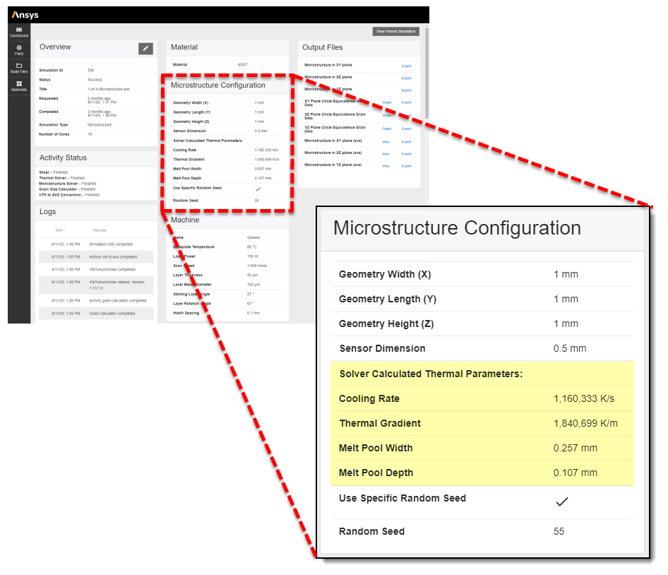
Use Provided Thermal Parameters - Check this option to bypass the full thermal solution and perform the microstructure solution only. (The Laser Power and Baseplate Temperature fields under Machine Configuration become disabled when you bypass the thermal solution.) Be aware that the Microstructure simulation run time increases proportionally with melt pool width and depth. The larger the Melt Pool Width, or the deeper the Melt Pool Depth, the longer the run time.
Cooling Rate (°K/sec) - Must be between 1x10⁵ and 1x10⁷. Defaults to 1x10⁶.
Thermal Gradient ( °K/m) - Must be between 1x10⁵ and 1x10⁸. Defaults to 1x10⁷.
Melt Pool Width (mm) - Must be between 0.075 and 0.8. Defaults to 0.15 mm.
Melt Pool Depth (mm) - Must be between 0.015 and 0.8. Defaults to 0.1 mm.
Random Seed
If desired, you can specify a specific random seed to be used as a starting point for the nucleation pattern. Use an integer between 0 and 4294967295. This feature allows you to generate the same output for the same inputs to check for repeatability. If you do not use a random seed (default), the solver will assign a random number for the nucleation starting point and simulation results will not be repeatable.