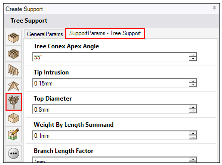
In addition to the general support parameters, parameters specific to tree supports allow you to control:
How the tree supports are generated, with trunks extending either toward the baseplate or toward the part
Characteristics of the uppermost branch tips that attach to the part (attachments), such as length and intrusion settings
The branch distribution across the support region, that is, the placement and spacing of branch tips as determined by several possible sampling techniques that each have their own settings
Note that there are no perforations or tooth patterns for tree supports and the ability to angle tree supports is not available.
Angle of the Tree Branches
The generation of tree supports begins with a point sampling distribution on the surface region. The algorithm starts by creating a cone of a certain apex angle, offset by a certain vertical distance, under each sampling point. A new branch is created wherever cones intersect. In this way, the tree is generated from the top to the bottom.
Tree Cone Apex Angle: The angle of the cone that is positioned after the offset under each sampling point. Larger angles result in many small branches at the top of the tree and a heavier trunk at the bottom. Smaller angles force the branches down to the baseplate such that an angle of 0° results in every branch reaching the baseplate, like in block supports. After several experiments, we chose a default angle of 55° for a reasonable amount of stiffness in the tree support structure.
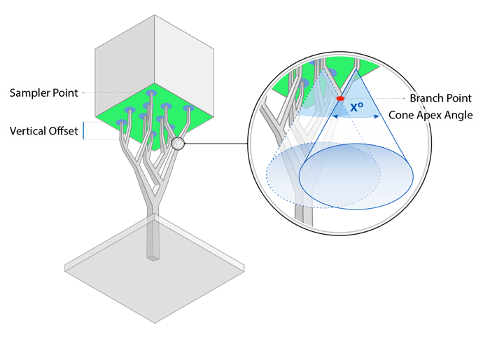
 Attachment Vertical Offset: If enabled, each branch tip is
offset by a certain amount before the start of the first cone.
Attachment Vertical Offset: If enabled, each branch tip is
offset by a certain amount before the start of the first cone.
 Attachment Vertical Offset Distance: The length of the vertical offset
before the first cone, in millimeters.
Attachment Vertical Offset Distance: The length of the vertical offset
before the first cone, in millimeters.
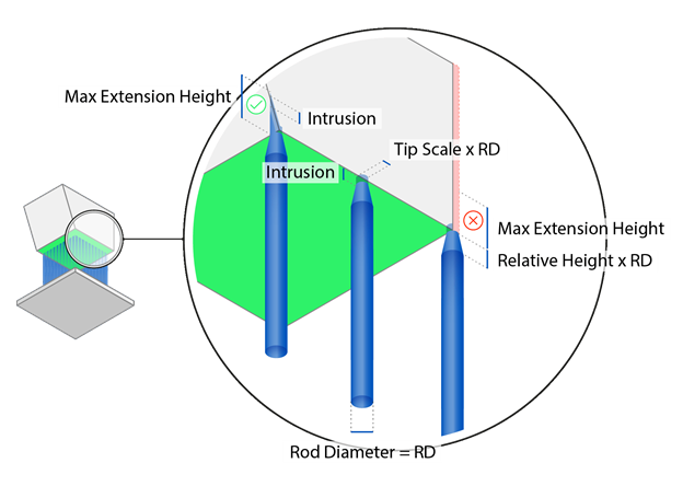
Tips of the Branches
Tip Height: The length of the tip attachment, in
millimeters.
Tip Scale: The scale (proportion) of the tip of the branch
relative to the branch's top diameter. For example, if Top Diameter is 0.8 mm and Tip Scale is
0.5, then the tip diameter will be 0.4 mm, which is half of the top diameter.
Tip Intrusion: The distance the tips of the tree branches penetrate into the part, in millimeters.
Tip Max Extension Height: The distance within which the tip
will attach itself to a mesh on both the inside and outside of an edge, chamfer, or step, in
millimeters. Depending on geometry, you may need to increase the Max Extension Height to ensure
attachment to a step or chamfer.
Top Diameter: The diameter of the top of a branch before the tip attachment, in millimeters.
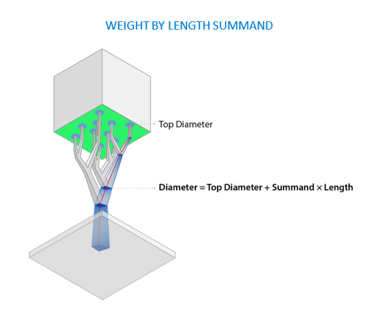
Weight (Thickness of Branches)
These parameters control the weight and, in effect, the thickening of the tree.
Weight By Length Summand: For a length of 1.0, the weight gets increased by the given factor. If two branches join, the weight of the longer branch is selected. Set to 0.0 by default to avoid any effect on the weight.
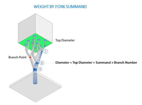
Weight By Fork Summand: At each fork, the given constant value gets added to the weight. Set to 0.0 by default to avoid any effect on the weight.
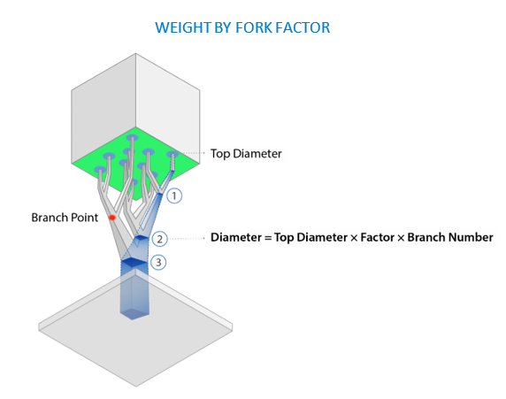
Weight By Fork Factor: At each fork, weight of the branch with the lesser weight gets multiplied by the given factor and is added to the total weight. Set to 1.0 to avoid any effect on the weight.
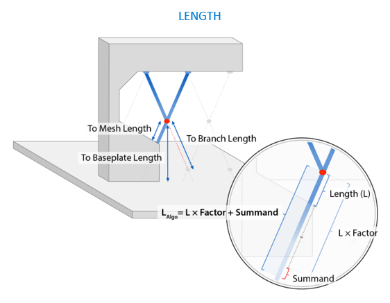
Length (Direction of Growth)
When length parameters are set to their defaults, a tree branch or trunk is built based upon which possible connection has the shortest length. There are three possible types of connections:
Branch to another cone/branch
Connect/attach to the part
Build down to the baseplate
You can drive the support generation algorithm by changing these connection lengths. Set the parameters such that the connections you do not want (for example, part-to-part supports) have the longest lengths. Factor and summand parameters work together to influence the direction of tree growth, either toward the part or toward the baseplate, and indirectly, how many tree branches there will be. Think of the set of factor parameters as the first level of control and the summand parameters as a finer level of control. Adjust the factors first and then generate the supports to see what the tree structure looks like. If you're not satisfied, adjust the summand parameters.
For better control, each length is multiplied by one of the factors. This way you can, for example, set a strong bias to avoid connections to the part. Set all factors to 1.0 for no effect (default).
Branch Length Factor: Multiplication factor for a connection to another branch intersection point.
Tree-to-Mesh (Part) Length Factor: Multiplication factor for a connection to the part.
Tree-to-Baseplate Length Factor: Multiplication factor for a connection to the baseplate.
Similar to the factors, the summands are constants that are added to each connection type. Set them to 0 for no effect (default).
Branch Length Summand: Value is added to the length of a connection to another branch intersection point.
Tree-to-Mesh (Part) Length Summand: Value is added to the length of a connection to the part.
Tree-to-Baseplate Length Summand: Value is added to the length of a connection to the baseplate.
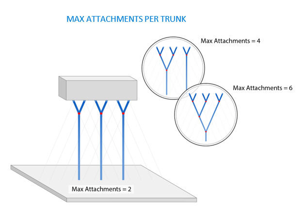
Maximum Attachments Per Trunk
Max Attachments Per Trunk: The maximum number of attachments that a single branch/trunk can support. If the limit is reached, a to-mesh or to-platform branch/trunk is built. A very large value results in one trunk.
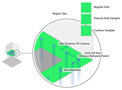
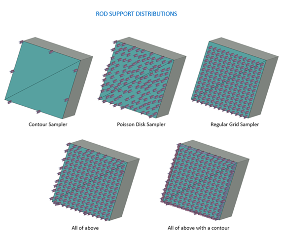
Branch Distribution
The spacing and pattern of how branches are distributed under a surface region are determined by one or more sampling selections. These distribution parameters are exactly the same as the rod support distribution parameters.
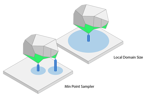
Use Min Point Sampler: If enabled, tree supports are generated
in a local minimum of a surface to be supported. This prevents geometries from being created
loose in the powder.
-
Min Distance to Outer Perimeter: The minimum distance between the tree
supports and the outer perimeter of the support region, in millimetres. (Note: This feature
applies even if a contour wall is disabled.)
-
Local Domain Size Distance: The diameter of a local minimum in which no
other minimum should be searched for, in millimeters. The diameter is shown as light blue
circles in the figures below.
Use Contour Sampler: If enabled, tree supports are generated
along the edges of the surface to be supported.
-
Min Distance to Outer Perimeter: The minimum distance between the tree
supports and the outer perimeter of the support region, in millimetres.
-
Min Distance Between Points: The minimum distance between the individual
branches of the tree support, in millimeters.
Use Regular Grid Sampler: If enabled, branches for the tree
support are generated at regular intervals for the selected surface to be supported. In doing
this, a fictitious cell is created for each branch of the tree support and the size of this cell
can be changed. In this way, you can define the minimum distance between the branches.
Min Distance to Contour: The minimum distance between the tree supports and the outer perimeter of the support region, in millimetres.
-
Grid Cell Size X: The width of the fictitious cell in the X-direction,
in millimeters.
-
Grid Cell Size Y: The width of the fictitious cell in the Y-direction,
in millimeters.
Use Poisson Disk Sampler: If enabled, tree supports are
generated and distributed for the surface to be supported based on a statistical Poisson distribution.
-
Min Distance to Outer Perimeter: The minimum distance between the tree
supports and the outer perimeter of the support region, in millimetres.
-
Min Distance Between Points: The minimum distance between the individual
branches of the tree support, in millimeters.
-
Seed: The starting point for the random generator for the Poisson
sampling distribution. If 0, the distribution is random for each regeneration of the tree
support. If Seed is set to a specific number >0, the branch distribution is deterministic and
therefore reproducible. A negative Seed value is not valid.