


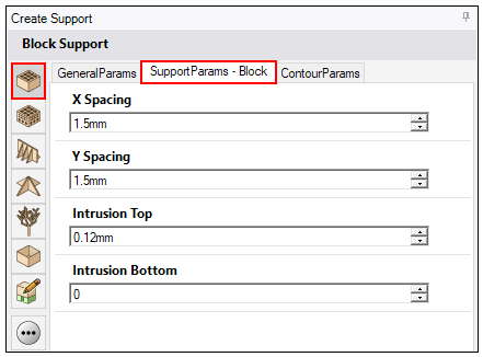
In addition to the general support parameters, parameters specific to block supports allow you to control:
Spacing and translation of the cells
How far the supports intrude into the part
Tooth-shaped cutouts at the upper and lower edges of supports
Perforations in the support walls
Clearance between vertical walls of the part and the supports
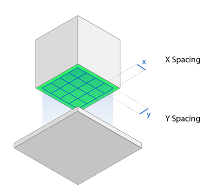
Spacing and Translation of Cells
X Spacing: The size of the block cells in the X-direction, in millimeters.
Y Spacing: The size of the block cells in the Y-direction, in millimeters.
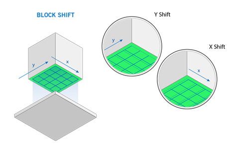
 X Shift: The translation of the block cells in the X-direction,
in millimeters.
X Shift: The translation of the block cells in the X-direction,
in millimeters.
Y Shift: The translation of the block cells in the Y-direction,
in millimeters.
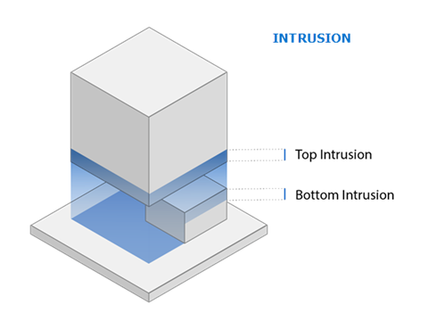
Intrusion into Part
It is common practice for supports to intrude, or penetrate, into part geometry. This ensures a good connection between the part and the support.
Intrusion Top: The distance the top of the interior support walls penetrate into the part, in millimeters.
Intrusion Bottom: The distance the bottom of the interior support walls penetrate into the part (for part-to-part supports), in millimeters.
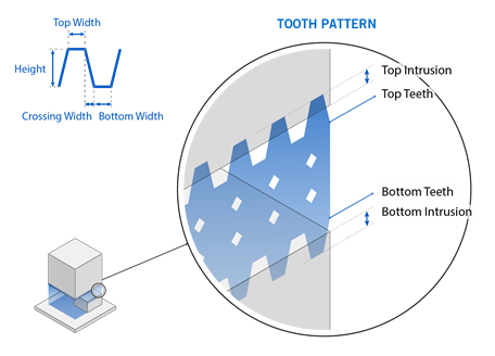
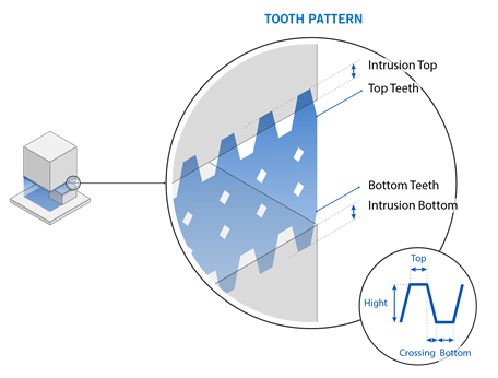
Tooth Pattern
Tooth patterns are tooth-shaped cut-outs at the upper and/or lower edges of each support wall. They can be generated between a part and the baseplate or between part areas. Their main purpose is to make it easier to remove supports.
 Create Top Tooth Pattern: If enabled, cut-outs are generated at
the upper edge of the interior support walls in the form of teeth. This is at the connection
between the support walls and the underlying part surface.
Create Top Tooth Pattern: If enabled, cut-outs are generated at
the upper edge of the interior support walls in the form of teeth. This is at the connection
between the support walls and the underlying part surface.
Top Tooth Bottom Width: The lower width of each tooth, in millimeters.
Top Tooth Crossing Width: The distance between the end of the top width and the start of the lower width, in millimeters. This affects the distance between teeth.
Top Tooth Width: The upper width of each tooth, in millimeters. A value of zero will produce a pointed tooth at the top, subject to intrusion settings.
Top Tooth Height: The height of the top tooth, in millimeters.
Create Bottom Tooth Pattern: If enabled, cut-outs are generated
at the lower edge of the interior support walls in the form of teeth. This is at the connection
between the support walls and the baseplate (or lower part surface).
Bottom Tooth Bottom Width: The lower width of each tooth, in millimeters. A value of zero will produce a pointed tooth at the intersection of the support walls and the baseplate (or lower part), subject to intrusion settings.
Bottom Tooth Crossing Width: The distance between the end of the top width and the start of the lower width, in millimeters. This affects the distance between teeth.
Bottom Tooth Top Width: The upper width of each tooth, in millimeters.
Bottom Tooth Height: The height of the bottom tooth, in millimeters.
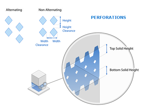
Perforate the Support Walls
Here you can define settings for perforations in interior block support walls.
Perforate the support walls: If enabled, perforations are generated.
Type: The shape of the perforations. A simple diamond is the only shape available.
Width: The width of the diamond, in millimeters.
Height: The height of the diamond, in millimeters.
Height Clearance: The distance between the diamonds in height—the height interval, in millimeters.
Width Clearance: The distance between the diamonds in width—the width interval, in millimeters.
Top Solid Height: The distance between the uppermost diamonds and the part at the top of the support wall, in millimeters.
Bottom Solid Height: The distance between the lowermost diamonds and the baseplate (or lower part) at the bottom of the support wall, in millimeters.
-
Alternate diamonds: If enabled, the diamonds will be
positioned offset to each other.
Check Part Clearance
Check Part Clearance: If enabled, you can define parameters for
the minimum distance between a vertical wall and supports. This avoids the collision of parts
and supports.
Clearance: The minimum distance between a vertical wall of the part and the support walls, in millimeters.
Collision Volume Vertical Offset: The vertical distance from a part surface in which the part clearance function is not applied, in millimeters. This creates a fictitious wall between the part and the area in which the part clearance function is applied.
Collision Volume Inclination: The angle of the fictitious wall from which the part clearance function is not applied, in degrees.