Unless you specified a base removal step, the only boundary condition that must be applied is a fixed support boundary condition on the build plate. If a base removal step is included, you need to apply fixed boundary conditions on three nodes of the part to prevent rigid body motion when the base is removed.
Procedural Steps
Under the Static Structural object, notice there is already an Imported Load object. This is the result of the linked analysis system and represents the temperature results from the transient thermal solution.
To fix the bottom surface of the base plate, right-click the Static Structural object and then select Insert > Fixed Support. Select the bottom surface of the base plate (geometry selection) and hit Apply in the Details view. If you have a more detailed geometry for the base, such as one with bolt holes that you want to explicitly simulate, apply the boundary conditions to affix the plate accordingly.
If you specified a base removal step, you must constrain the part at three nodes to prevent rigid body motion. Be aware that you will be constraining the nodes to their displaced position at the end of the build, rather than constraining them to 0. (For example, if the node displaced 0.1 mm during the simulation, the constraint will keep the node at 0.1 mm.) Use a Commands object to do this, as follows:
You may want to hide the base body during this process. Right-click the base body and select Hide Body.
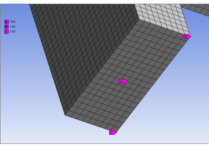
Zoom in to the area of the part where you will apply constraints. Switch to Node mode of selection.
Create nodal named selections: Right-click Model in the project tree, and select Insert > Named Selection. Select a node on the bottom of the part, perhaps toward the middle of the part. You should choose nodes that are unimportant to your results. Perhaps spread them out over the bottom of the part but the nodes must not be co-linear. Your node selection will affect displacement results but not stresses or strains. Click Apply in Details. Right-click the newly created Selection in the project tree (under Named Selections) and select Rename. Name it to something short and descriptive, such as CN1 (for constrained node 1). Do the same step two more times and rename them to CN2 and CN3.
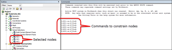
Create commands to constrain the nodes: Click the Static Structural object and select Commands
 from the context menu. Or,
right-click and select Insert > Commands. In the Commands window that is displayed, copy and paste, or type, the
following:
from the context menu. Or,
right-click and select Insert > Commands. In the Commands window that is displayed, copy and paste, or type, the
following:D,CN1,UX,%_FIX% D,CN1,UY,%_FIX% D,CN1,UZ,%_FIX% D,CN2,UY,%_FIX% D,CN2,UZ,%_FIX% D,CN3,UZ,%_FIX%
Constrained node 1 is fixed in UX, UY, and UZ and holds the part in place. Constrained node 2 is fixed in UY and UZ, and constrained node 3 is fixed in UZ; these prevent rotation. Selection of CN1 can have a big effect on the displacement throughout the part. See the D command, which defines degree-of-freedom constraints at nodes, for more information.
Match the commands to the base removal sequence step: Select the newly created Commands object under Static Structural and, in Details, change the Step Selection Mode to By Identifier. Change the Step Number to Removal Step: Base. This ensures the constraints are applied just before the base removal step.
Remember to make the base plate visible again if you hid the body. Right-click the base body and select Show Body.