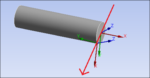
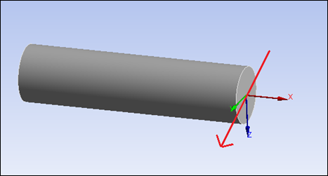
A ray cast starts at a point and moves along a vector, finding geometry it intersects with along the path. With each intersection point, the normal of the intersected geometry can be determined. While Ansys uses this algorithm internally for many purposes, such as Hit Point Normal axis selection for coordinate systems, you can use it for your own purposes, such as defining coordinate systems.
To perform ray casting in Mechanical, use the method CastRayOnGeometry(), calling it like this:
Ansys.Mechanical.Selection.SelectionHelper.CastRayOnGeometry
The method CastRayOnGeometry() has the following inputs:
| Method Input Name | Type | Functionality |
|---|---|---|
castVector | BoundVector | Starting location and direction of the ray cast. |
settings (Optional. Descriptions of
defaults are provided later in this topic.) | GeometryRayCastSettings
| Dictates how and what geometry entities should be hit and returned on the method call. |
The inputs return a list of GeometryRayCastHit objects:
| Method Output Name | Type | Functionality |
|---|---|---|
HitVector | BoundVector | Starting location and unit direction on the geometry entity of the ray cast hit. |
Entity | IGeoEntiry | Geometry entity hit by ray cast. |
GeometryRayCastSettings can be used to customize the behavior of the ray cast algorithm. It contains the following properties:
| Setting Property Name | Type | Description |
|---|---|---|
HitFaces | bool | Specifies if ray cast hits should return faces. Defaults to true. |
HitEdges | bool | Specifies if ray cast hits should return edges. Defaults to false. |
HitVertices | bool | Specifies if ray cast hits should return vertices. Defaults to false. |
HitBodies | bool | Specifies if ray cast hits should return bodies. Defaults to false. |
MaxHits | int | Specifies the maximum number of ray cast hits. Defaults to 1000. |
CastRadius | Quantity | Specifies the maximum distance normal to the
castVector qualifying as a hit. In other
words, it is the cylinder around the
castVector that intersects the geometry.
Defaults to 1/500 the average of the overall bounding box. |
CastLength |
Quantity | Specifies the maximum distance along the
castVector from the
castVector origin. Defaults to go through
all. |
Example 1
This code creates a bound vector from which the ray cast originates and then casts it into the geometry as indicated earlier:
a_point = Point([2000,2000,2000], 'pm')
a_vector = Vector3D(-1,0,0)
a_bound_vector = Ansys.Mechanical.Math.BoundVector(a_point, a_vector)
The result is used to create (or modify) a coordinate system by setting its
PrimaryAxisDirection, Origin, and
OriginDefinedBy to the output
BoundVector to create a coordinate system for each geometry
hit, visualizing the hit points and directions from the ray cast:
geom_hit = Ansys.Mechanical.Selection.SelectionHelper.CastRayOnGeometry(a_bound_vector)
for geom in geom_hit:
    print("\nNew geometry collision - " + str(geom.Entity.Type))
    print(geom.HitVector.Vector)
    print(geom.HitVector.Origin)

    cordSName = "Hitpoint " + str(list(geom_hit).index(geom))
    cordS = ExtAPI.DataModel.Project.Model.CoordinateSystems.AddCoordinateSystem()
    cordS.Name = cordSName

    cordS.PrimaryAxisDirection = geom.HitVector.Vector
    cordS.Origin = geom.HitVector.Origin.Location
    cordS.OriginDefineBy = CoordinateSystemAlignmentType.Fixe
The following images show output from the code:


Example 2
This code shows an example of changing ray cast settings, run with the same for loop in the second block as in the previous example:
a_point = Point([2000,2000,2000], 'pm')
a_vector = Vector3D(-1,0,0)
a_bound_vector = Ansys.Mechanical.Math.BoundVector(a_point, a_vector)
cast_settings = Ansys.Mechanical.Selection.GeometryRayCastSettings()
cast_settings.HitBodies = True
cast_settings.HitFaces = False
geom_hit = Ansys.Mechanical.Selection.SelectionHelper.CastRayOnGeometry(a_bound_vector, cast_settings)
The following images show output from the code:


