T-joints are used to bond a primary structure to a secondary one. A good example is a frame with a stringer of a boat hull. Oriented Selection Sets (OSS) allow you to define complex laminates by an intuitive approach. For an example of a T-Joint analysis, see T-Joint Tutorial.
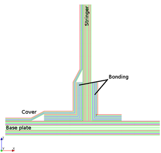
The laminate of a T-joint can be split into several sublaminates:
Base plate (skin)
Stringer (frame)
Bonding
Cover
The laminate is modeled by defining different Oriented Selection Sets for the different regions. The modeling plies are then associated with the OSS and their order defines the stacking sequence of the laminate.
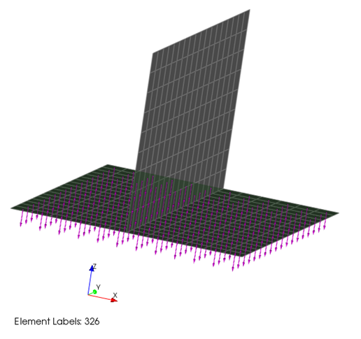
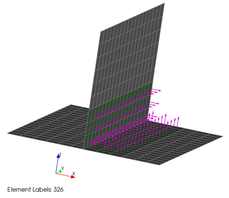
The first OSS is defined for the base. The offset direction of this OSS shows from top to bottom as shown in Figure 3.2: OSS for the Base Plate.
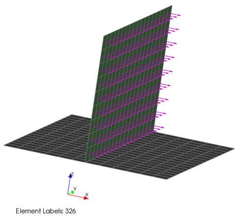
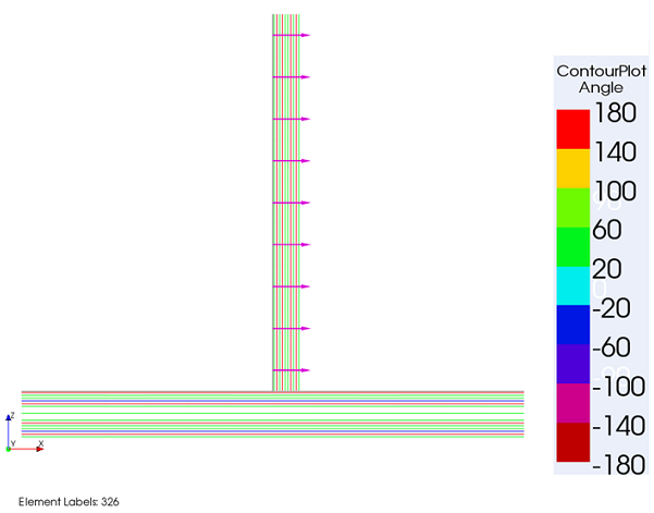
The OSS of the string has an orientation parallel to the global X-direction as shown in Figure 3.3: OSS for the Stringer.
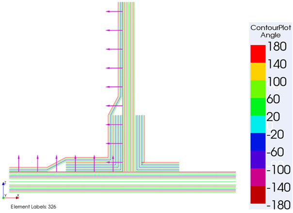
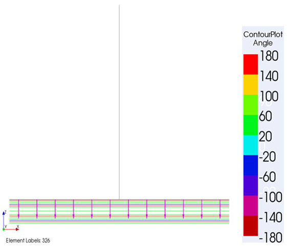
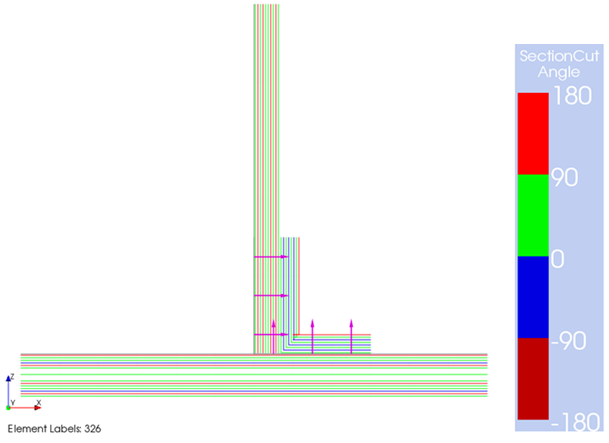
The OSS feature allows you to define several offset directions for one element: OSS can overlap and can have different orientations. This functionality is used to define the offset direction for the bonding layers as shown in Figure 3.4: OSS for Bonding Plies. The offset direction of the base plate is different if compared with Figure 3.2: OSS for the Base Plate.
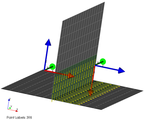
In addition, the OSS feature allows you to define the reference directions for complex shapes (twisted surfaces, right angles). The reference direction is computed from one or several reference coordinate systems (CSYS) as shown in Figure 3.5: Reference Direction. In this case two CSYS are selected.
After all the necessary OSS are defined, define the Modeling Plies in the same order as the structure is produced later. First, the base lay-up is defined using the OSS of the base plate.
The next plies are added to the stringer.
It is important to define the base plate and stringer laminate before the bonding plies are defined because the order is responsible for the final offset. As shown in Figure 3.8: First Bonding Laminate, the bonding layers are applied to the top of the base plate and onto the plies of the stringer.
On the other side, the second bonding laminate is offset to the top (base plate) and to the left (stringer).

Cover plies complete the lay-up definition of the T-joint. Figure 3.10: Cover Plies shows that ACP can also handle Drop-Offs.