


The draping algorithm is described in Draping Simulation.
Draping Method Definition
The draping effect depends highly on the manufacturing process. Process-relevant values can be defined in the ACP draping algorithm.
Seed Point
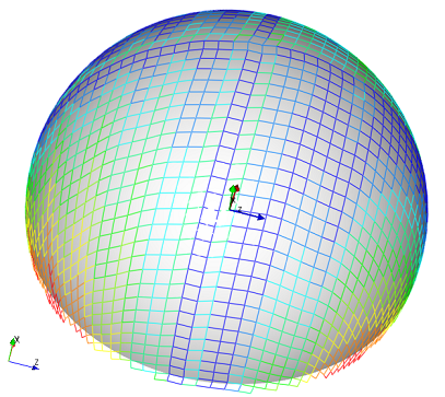
The Seed Point is the starting point where the ply is laid into the mold. At this location the fiber direction is unchanged and the draped fiber direction is equal to the theoretical one. The Seed Point can have a big influence on the final result of the draped fiber angles. Assuming a half sphere and a Seed Point located on the pole, the maximum draped fiber angle is much smaller than the same evaluation with a Seed Point on the equator. The Seed Point corresponds to the first element of the draping mesh (left representation in Figure 5.1: Draping Scheme ).
Draping Direction
After the first point is applied on the mold, the Draping Direction defines along which route the ply is laid into the mold. The draping algorithm first walks along the Draping Direction, then orthogonal and finally proceeds with the 45-degree zones. Figure 5.1: Draping Scheme shows the scheme in which the ply is applied.
Draping Mesh
The draping algorithm minimizes the shear energy dissipation where an internal Draping Mesh is used for the evaluation. This mesh is independent from the structural mesh and has its own size. Analog to the structural mesh, the optimal Draping Mesh size is established by balancing the precision of the draping evaluation and the computational cost.
In the case of an incomplete draping, select another Seed Point, define a different Draping Direction and/or change the Draping Mesh size. The draping mesh is built as shown in Figure 5.1: Draping Scheme .
Draping Definition on OSS Level
The draping can be activated in the Draping tab of the Oriented Selection Set Properties dialog.
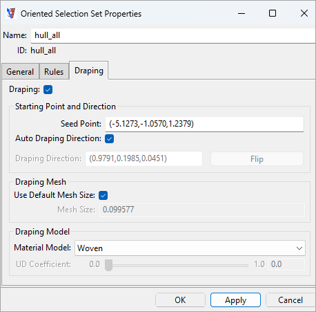
If draping is activated on the OSS level, the Reference Direction of the OSS is adjusted and all associated modeling plies use this draped reference direction. If the Modeling Ply also has an active draping definition, then an independent draping simulation is started for the modeling ply.
Draping Definition on Modeling Ply Level
Just like OSS, draping can be activated on the Modeling Ply level. To activate the draping you toggle the Draping check box and define a Seed Point. By default, the Mesh Size and Draping Direction are evaluated automatically.
By default, during the draping simulation the draping mesh is laid on the reference surface of the model independently of the lay-up thickness. If the model property Use Draping Offset Correction is enabled, the draping mesh follows the bottom offset (relative to the reference surface orientation) of the selected ply, thus taking into account the lay-up thickness.
An additional feature, Thickness Correction, is implemented in the Internal Draping algorithm. Due to the shear deformation, the fiber direction and thickness of the ply change. This change can also be considered by activating the Thickness Correction option.