


Cuntze's approach is based on his general invarient-formulated failure mode concept (applicable for isotropic and orthotropic materials), applied here to transversely isotropic UD materials. This concept strictly separates the 5 strength failure modes inherent to UD materials. Material symmetry requires strength measurements in 5 directions, and physical fracture morphology dictates that each failure mode is dominated by strength in a single direction only.
Cuntze's strength of failure conditions (SFC) can be termed modal conditions according to the fact that a failure function F describes just one failure mode and involves just the mode-associated strength:
 | (5–100) |
with the vector of 6 stresses  .
.
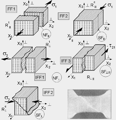
A set of modal SFCs requires an interaction of the 5 failure modes. The observed failure modes are two fiber failure modes (FF1 tension, and FF2 compression) and three interfiber failure modes (IFF1 transverse tension, IFF2 transverse compression, and IFF3 shear) which represent cohesive and adhesive matrix failures between fiber and matrix.
Cuntze provides equivalent stresses for all 5 fracture failure modes of the brittle-behaving UD material similarly to the Hencky-Mises-Huber yielding failure mode of ductile-behaving materials.
An equivalent stress  includes all stresses that are acting together in a given failure mode. The
vector containing all equivalent stresses is:
includes all stresses that are acting together in a given failure mode. The
vector containing all equivalent stresses is:
 | (5–101) |
where an equivalent stress is related to the mode strength and the material stressing
effort  by:
by:
 | (5–102) |
 | (5–103) |
where the overbar marks statistical average values and the mode strengths can be substituted by the respective material stress limits.
In addition to the 5 strengths, Cuntze uses two material-inherent fracture parameters,  (required by Mohr-Coulomb), because SFCs for brittle-behaving materials
cannot be based on strength values alone. Macromechanical SFCs must consider that materials
fail on the micromechanical level, with respect to the fiber failure modes.
(required by Mohr-Coulomb), because SFCs for brittle-behaving materials
cannot be based on strength values alone. Macromechanical SFCs must consider that materials
fail on the micromechanical level, with respect to the fiber failure modes.
Five invariants are used for the generation of the five SFCs (2D or 3D) [ 17 ]:
 | (5–104) |
Replacing the invariants in Cuntze's invariant formulated SFCs [
19
]
[
20
] with the
associated stress states (factoring in IFF3 not the full stress state components but just the
mode failure driving stress) and resolving for the simplified material stressing efforts  yields the following:
 | (5–105) |
where the superscripts  and
and  stand for tension and compression, respectively.
The friction parameter  can be computed from the available friction coefficients of the UD material,
derived in [
20
]
can be computed from the available friction coefficients of the UD material,
derived in [
20
]
 | (5–106) |
with typical ranges being:

|

|
If measurement data of the fracture angle is given, the friction coefficient  is determined as:
 | (5–107) |
or the directly related parameter  as:
as:
 | (5–108) |
where  .
.
If the IFF2 and IFF3 curves are based on enough test data, the 2 friction parameters can be determined using the following formulas [ 20 ]:
 | (5–109) |
An interaction of the failure modes occurs due to the fact that the full (global) failure
surface consists of five parts. Cuntze models these interactions by a simple,
probability-based series spring model [
17
]. This
model describes the lamina failure system as a series failure system which fails whenever any
of its elements fail. Each mode is one element of this failure system and is treated as
independent of the others. By this method, the interaction between FF and IFF modes as well as
between the various IFF modes acts as a rounding-off procedure, enabling the determination of
the final  or inverse reserve factor (IRF).
 | (5–110) |
In other words, the interaction equation includes all mode stressing efforts, and each of them represents a portion of the material's load-carrying capacity. In 2D practice at maximum 3 of the 5 modes will interact.
The modes' interaction exponent  is obtained by curve-fitting of test data in the interaction zones.
Experimental data showed that (for CFRP)
is obtained by curve-fitting of test data in the interaction zones.
Experimental data showed that (for CFRP)  .
.
The exponent  is high in case of low scatter and low in the case of high scatter, hence
chosing a low value for the interaction exponent is conservative. As an engineering
assumption,
is high in case of low scatter and low in the case of high scatter, hence
chosing a low value for the interaction exponent is conservative. As an engineering
assumption,  is always given by the same value, regardless of the distinct mode
interaction domain.
is always given by the same value, regardless of the distinct mode
interaction domain.
For pre-design, Cuntze recommends  and
and 

