In this section, you will first define the input parameters in ACP (Pre) and output parameters in Mechanical and ACP (Post). Then, you will create multiple design points to evaluate the results of different lay-up scenarios.
Follow these steps to create input parameters based on the modeling plies' angles:
In Workbench, double-click the Setup cell in the ACP (Pre) system to open ACP.
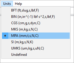
In the ACP's toolbar, click Units and select MPA (mm,t,s,N,C).
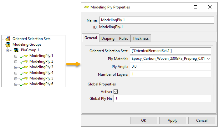
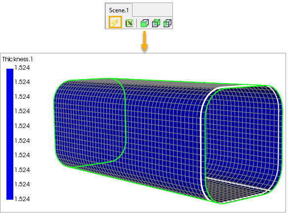
Six 0° modeling plies were defined for the project. Double-click each ply in the ACP's Tree View to examine its properties.
Update the model to view the thickness of the lay-up.
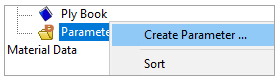
In the Tree View, right-click Parameters and select Create Parameter.
In the Parameter Properties dialog, change the parameter's name to
ModelingPly.1.ply_angle(A, below). Place the cursor in the Object field (B) and select ModelingPly.1 from the Tree View. Specify the other properties as shown (C), then click Apply and close the dialog.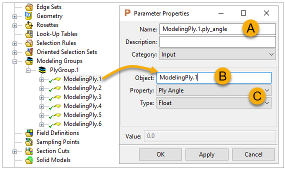
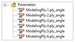
Follow steps 5 and 6 above to create five more parameters for the other modeling plies, then close ACP.
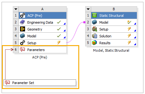
In Workbench, the Parameter Set system has been created and connected to the ACP (Pre) system. Double-click either cell to open the Parameters tab.
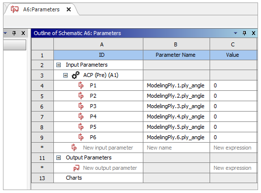
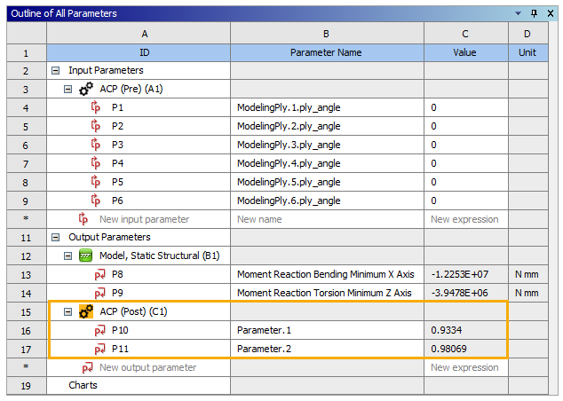
Examine the Input Parameters' properties, then close the tab.
Follow these steps below to examine the bending and torsional loads in Mechanical, then define the output parameters from these loads.
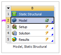
In Workbench, double-click the Model cell in the Model, Static Structural system to open Mechanical.
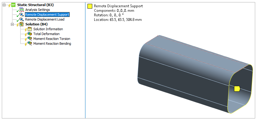
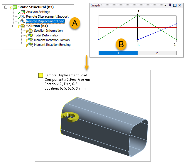
Click Remote Displacement Support in the tree Outline to view it in the model.
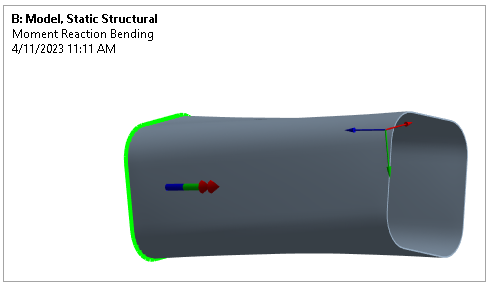
There are two load steps for this model. Select Remote Displacement Load (A), then click step 1 in the Graph pane (B) to view the bending load.
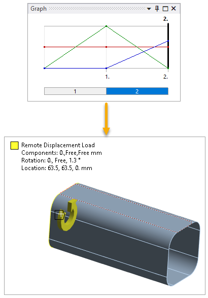
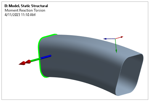
Switch to step 2 to view the torsional load on the model.
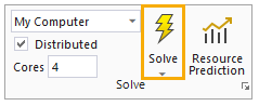
In the Home tab, Solve the model.
In the tree Outline, select Total Deformation under Solution to view the deformation plot.
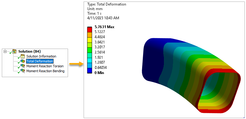
In the Graph panel, click the
 icon to view the
deformation changes through time.
icon to view the
deformation changes through time.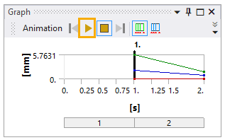
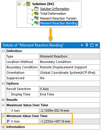
Repeat steps 6 and 7 above to view the Moment Reaction Torsion and the Moment Reaction Bending.
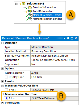
In the tree Outline, click Moment Reaction Torsion (A, below). In the Details pane, check Z Axis under Minimum Value Over Time (B) to make it a parameter.
Follow the previous step to create another parameter from Moment Reaction Bending using the properties shown below.
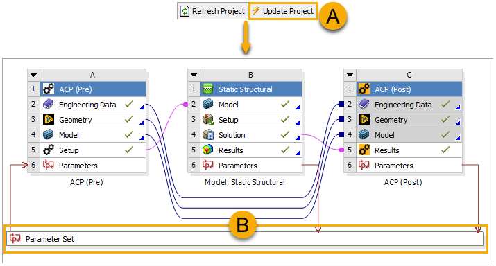
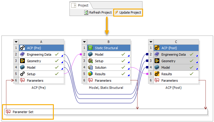
Close Mechanical. The Parameter Set cell connects the input and output parameters from the two systems. In Workbench, update the project (A), then double-click Parameter Set (B) to view the results.
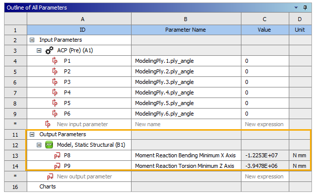
In the Parameter Set tab, examine the Output Parameters values, then close the tab.
In this section, you will define two expression output parameters in ACP (Post) based on the failure results. An expression output parameter is created using a Python script.
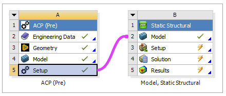
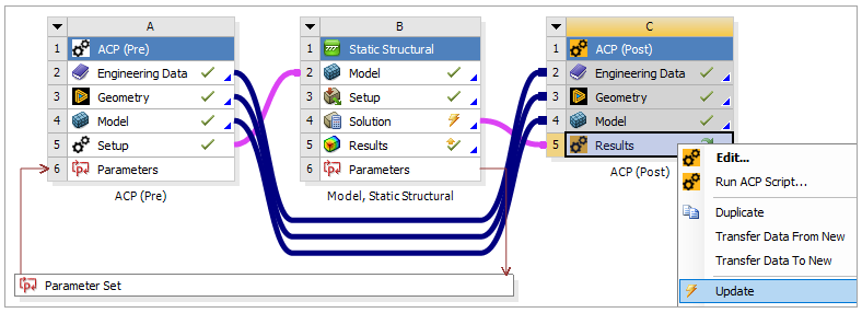
In Workbench, click ACP (Post) under Component System in the Toolbox, then drop it onto the ACP (Pre) system (A, below).
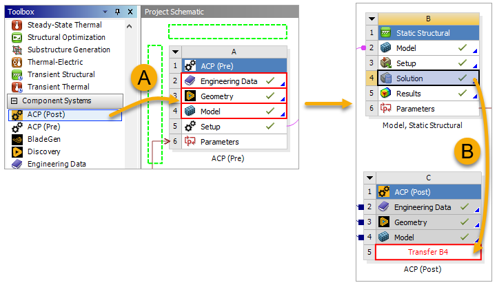
Click the B4 Solution cell in the Model, Static Structural system and drop it onto the C5 Results cell of the ACP (Post) system (B, above) to connect the two cells.
Right-click the Results cell of the ACP (Post) system and select Update, then double-click the cell to open ACP.
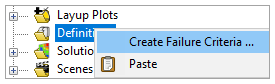
In the Tree View, right-click Definitions and select Create Failure Criteria.
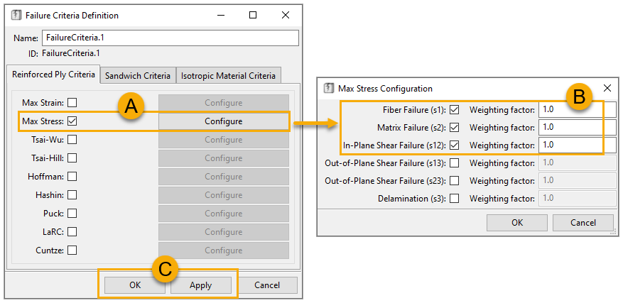
In the Failure Criteria Definition dialog, activate Max Stress and click Configure (A). In the Max Stress Configuration dialog, specify the properties as shown (B), then close the dialog. Click Apply, then click OK (C).
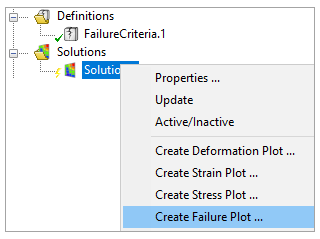
In the Tree View, expand Solutions, then right-click Solution.1 and select Create Failure Plot.
In the Failure dialog, define the properties as shown, then click Apply and close the dialog.
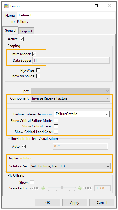
Note: The Solution Set option specifics the load or time step for which the results display in Mechanical.
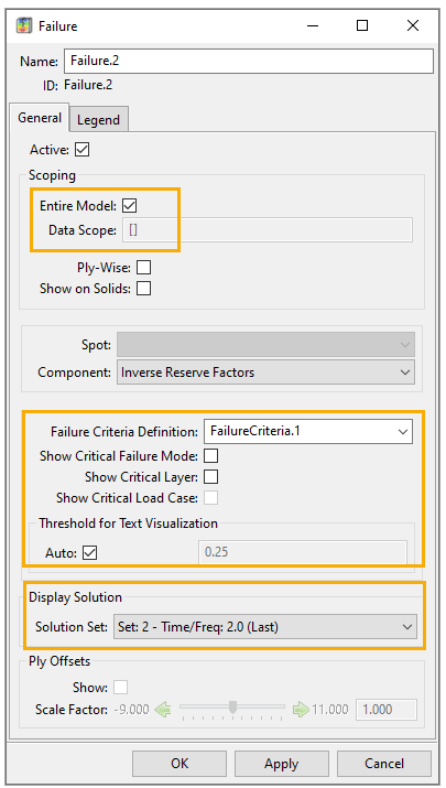
Follow steps 6 and 7 above to create Failure.2 using the specifications shown below.
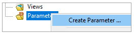
In the Tree View, right-click Parameters and select Create Parameter.
In the Parameter Properties dialog, change the Category to Expression Output (A). Clear the Source field, then add the script below into the field to create a parameter based on Failure.1 (B):
return_value = db.active_model.solutions["Solution
                            1"].plots["Failure.1"].minmax[1]
Click Apply and close the dialog.

Follow steps 9 and 10 above to create the second parameter based on Failure.2 using the script below:
return_value = db.active_model.solutions["Solution
                            1"].plots["Failure.2"].minmax[1]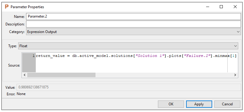
Close ACP. In Workbench, update the project again, then double-click Parameter Set.
In the Parameter Set tab, examine the ACP (Post)'s Output Parameters values.
A design point is a single set of parameter values representing one design alternative. Each design point is a snapshot of your design given a set of input parameter values, where output parameter values are calculated by updating the project. Design points enable you to perform what-if studies. Follow these steps to create additional design points to get the results from various lay-up settings:
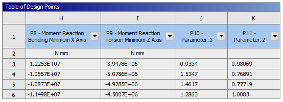
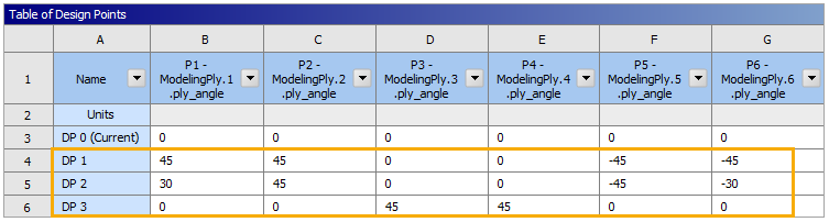
Open the Table of Design Points in the Parameter Set tab and add three design points using the ply angles shown below.
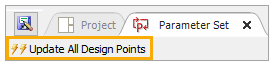
Click Update All Design Points to compute the output parameter results for the design points.
Examine the output values to evaluate which design point results in a more optimized model, then close the Parameter Set tab.