The goal of this tutorial is to compute homogenized material data for a UD composite. In this tutorial, the data from Younes et. al (2012) will be reproduced.
Use the following procedures to compute homogenized material data for a UD composite:
Initialization
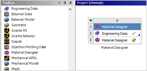
Open Ansys Workbench.
Drag a Material Designer component system to the project schematic.
Define Input Materials
Double click the Engineering Data cell of the Material Designer component system.
Define a new material for the fiber.
Add a new material and name it
Carbon.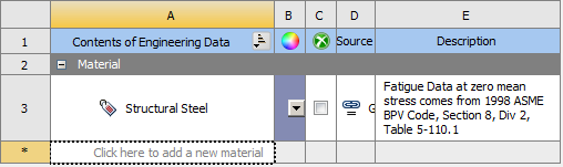
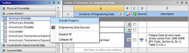
From the Toolbox on the left, add the Orthotropic Elasticity property.
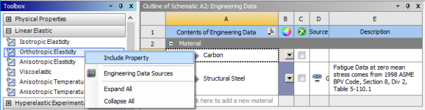
Add the following orthotropic elasticity properties:
Young's Modulus X 232 GPa Young's Modulus Y 15 GPa Young's Modulus Z 15 GPa Poisson's Ratio XY 0.279 Poisson's Ratio YZ 0.49 Poisson's Ratio XZ 0.279 Shear Modulus XY 24 GPa Shear Modulus YZ 5.033577 GPa Shear Modulus XZ 24 GPa 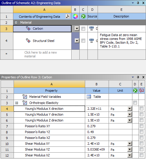
Note: We assume that the fiber is transversely isotropic and use the relationship
 .
.
Define a new material for the matrix.
Add a new material and name it
Epoxy.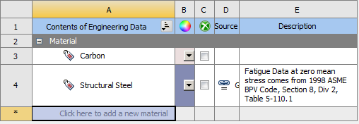
From the toolbox on the left, add the Isotropic Elasticity property.
Add the following isotropic elasticity properties:
Young's Modulus 5.35 GPa Poisson's Ratio 0.354 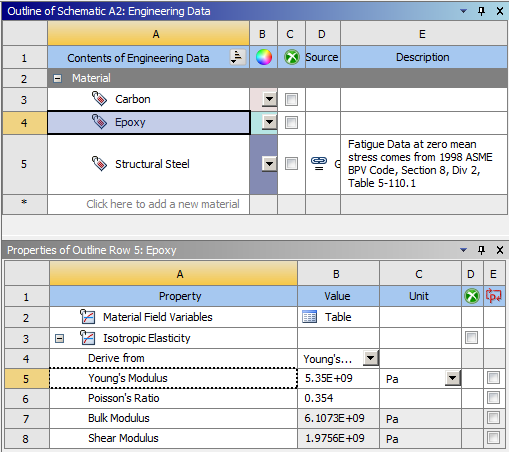
Return to the project schematic.
Design Material
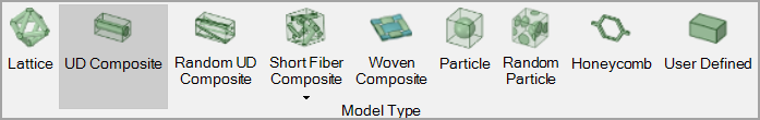
Double-click the Material Designer cell of the Material Designer component.
Click UD Composite in the Ribbon Bar.
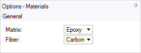
Click Constituent Materials in the Ribbon Bar.
Assign the Epoxy material to Matrix.
Assign the Carbon material to Fiber.
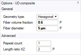
Click Geometry in the Ribbon Bar.
Set Geometry Type to Hexagonal.
Set Fiber Volume Fraction to 0.6.
Set Fiber Diameter to 5 µm.
Click Complete (
 ) to create an
RVE.
) to create an
RVE.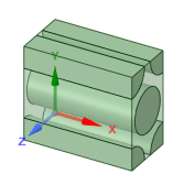
Click Mesh in the Ribbon Bar.
Activate Use Conformal Meshing and Use Block Meshing.
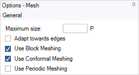
Click Complete (
) to obtain a conformal,
block structured mesh.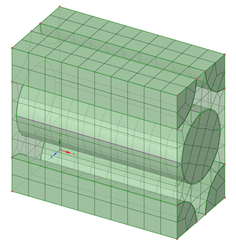
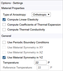
Click Analysis Settings in the Ribbon Bar.
Uncheck the Use Periodic Boundary Conditions option. This RVE has reflectional symmetries that allow the use of non-periodic boundary conditions without introducing boundary effects.
Click Constant Material in the Ribbon Bar.
Set the Material Name of the new material to
Epoxy Carbon UD.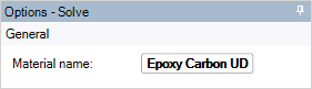
Click Complete (
) to obtain results. You
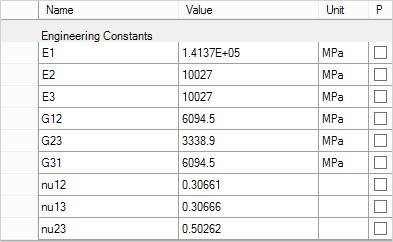
need to wait until all load cases are solved before proceeding.Review the results by clicking the Results item in the outline.
In the Results view, you can review calculated material properties such as Young's Modulus, Poisson's Ratio, and Shear Modulus. You can select values and copy them to the clipboard using the Context Menu or by pressing Ctrl+C.
Design Variable Material
The above procedures produced homogenized material data for a composite material. It is possible to investigate how altering certain properties of the material will alter its final homogenized properties. Simulate the effects of changing the fiber volume fraction using the following procedure:
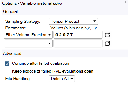
Click Variable Material in the Ribbon Bar.
Choose Fiber Volume Fraction as the Parameter.
Set the parameter values as
0.2-0.7:7. This notation represents a sampling interval from 0.2 to 0.7 with 7 total samples.Leave all other fields at the default.
Click Complete (
) to obtain results. The
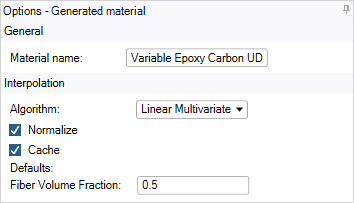
calculations will take a few minutes to complete.Click Generated Material in the Outline and set the Material Name to Variable Epoxy Carbon UD. In addition, set a default Fiber Volume Fraction of 0.5.
Click Complete (
) to
finish the generation of the variable material.Review the results by clicking the Results item in the outline.
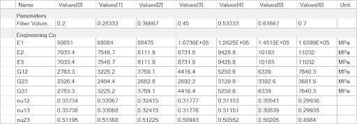
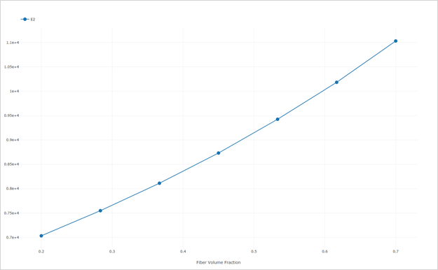
Right-click the Variable Material Evaluation item in the outline and click Add Chart.
In the chart options, activate E2.
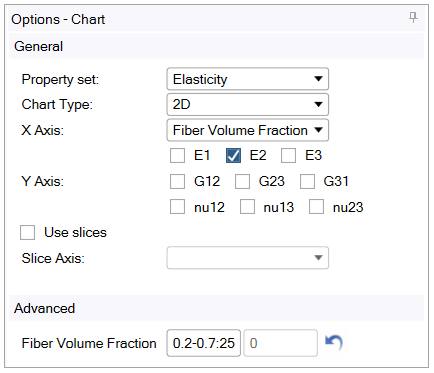
Click Complete (
) to obtain the
chart.Review the visualized material in the Chart tab.
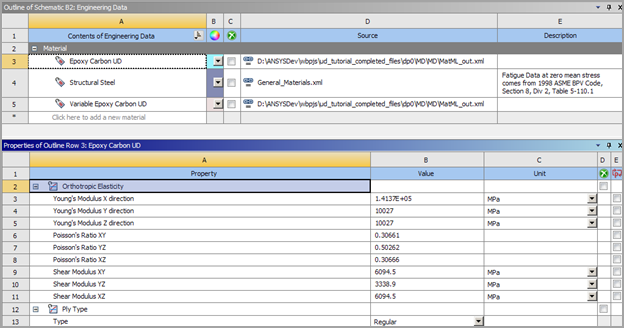
Review Materials in Workbench
Computed materials can be passed to downstream analyses by connecting the Material Designer cell of the Material Designer component system to an Engineering Data cell. Use the following procedure to pass the homogenized material data to a downstream analysis system:
In the project schematic in Workbench, add an Engineering Data component system and link the Material Designer cell to the Engineering Data cell.
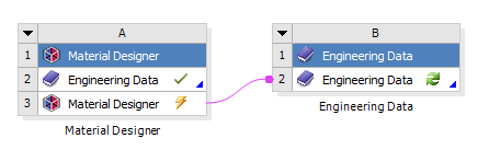
Right-click the Engineering Data cell of the downstream component system and select Update.
Double-click the Engineering Data cell of the downstream component system and review the materials in the Engineering Data screen. The computed materials are available and can be used in further analysis steps like any other material.