


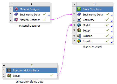
Simulating the thermo-mechanical behavior of short fiber reinforced composites poses a challenge to the materials engineer, but Ansys Workbench provides a streamlined workflow which makes the process much more manageable. The workflow, illustrated in the figure below, consists of three parts:
In Material Designer: Using Material Designer's homogenization technology, characterize the macroscopic response of the composite material (represented in system A below).
Using the Injection Molding Data system (system C below), import injection molding simulation results from other software tools. Then use Ansys Mechanical to map the model.
Setup of a Mechanical analysis system for simulating the part (system B).
The building blocks of the workflow are flexible, so you can adapt them to different needs and more advanced requirements. In all cases, short fiber workflows in Workbench are based on the principle that the material characterization should be independent of the part simulation. The workflow, therefore, uses a sequential (as opposed to concurrent) homogenization approach. As a result, the outcome of the microstructure homogenization performed in Material Designer becomes a regular material stored in the Engineering Data. This homogenized material is later fed into the structural solver without any further linking to the microstructural system. Once the homogenization has been performed, you can use the resulting material for simulating several parts, provided they are made of the same composite material.
Note: Short fiber workflows in Workbench only support solid geometries. Surface (shell) bodies are not supported.
The next section describes in more detail the methodology underlying the workflow described above.
As already mentioned, the most important factors in a short fiber reinforced composite simulation are the influences of the microstructure and that of the manufacturing process. In the case of injection molded parts, the manufacturing process induces a complex, locally varying fiber-orientation distribution which significantly affects the mechanical performance of the final part. Because the orientation distribution cannot be directly computed for an entire part, injection molding simulations usually predict only its second statistical moment, the so-called (second order) fiber orientation tensor. Several dedicated software tools exist to perform this type of simulation. Typically, their output is a fiber orientation tensor field defined either at the nodes or at the element centroids of the injection molding simulation mesh (which is usually different from the structural mesh).
The following section explains how to capture the influence of the fiber orientation tensor on the overall anisotropic properties of the composite.
The fiber orientation tensor  is a symmetric positive semi-definite 3 x 3 tensor with trace
equal to one. Therefore, it admits a spectral decomposition of the form
is a symmetric positive semi-definite 3 x 3 tensor with trace
equal to one. Therefore, it admits a spectral decomposition of the form
 | (1–1) |
where
 is a rotation matrix whose columns
  represent the principal fiber directions.
 is a diagonal matrix of eigenvalues (sorted in decreasing
order) with
is a diagonal matrix of eigenvalues (sorted in decreasing
order) with  . Moreover,
 | (1–2) |
In general, the mechanical properties of the homogenized material depend on the full orientation tensor. However, if the local coordinate system is set to coincide with the principal fiber directions, the response of the material depends only on the two largest eigenvalues of the orientation tensor.
Based on this observation, Ansys short fiber workflows build upon a three-step procedure:
Prior to and independently of the part simulation: Characterize the homogenized material for carefully selected sample orientations in the region of
 defined by Equation 1–2. This
produces a variable material whose properties depend on
defined by Equation 1–2. This
produces a variable material whose properties depend on  and
and  .
.For each given point on the injection molding mesh, decompose the fiber orientation tensor into its eigenvalues and eigenvectors.
Import the eigenvalues and eigenvectors of the orientation tensor as element orientations and material fields, respectively. Then map them onto the structural mesh. During the analysis, the element-wise material properties are obtained by querying the variable material for the value of
 assigned to each element.
The next sections describe in more detail how to set up the workflow in each individual component, namely Engineering Data, Material Designer, Injection Molding Data, and Mechanical.