Using the Illuminance Cone Diagram
The page shows how to use the Illuminance Cone Diagram.
To use the Illuminance Cone Diagram:
-
Click Illuminance Cone Diagram
 .
.
-
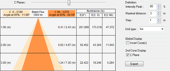
Set the Illuminance Cone Diagram Definition parameters:
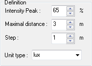
- Intensity Peak: percentage of the maximum intensity of the source.
- Maximal distance: distance between the apex of the cone and the base of the cone.
- Step: interval between two mounting distances.
- Unit type: defines the illuminance unit between lux (SI) and foot candle (US).
-
According to the context, in the Global Display section, check Invert
Cone(s).
-
To display the cone representing the percentage of intensity peak specified, in the 2nd Cone Display section, check
C Plane.