


Interpolation Enhancement Overview
BSDF measurements are done at finite incidence angles determined by user.
In simulation, the BSDF data file applied as optical surface property to a given surface contains data that allows Speos to know how a ray arriving with one of the incidence angles at the surface is reflected and diffused.
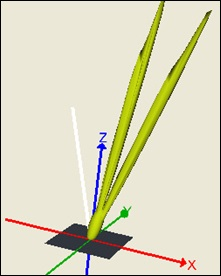
The following example illustrates the BSDF interpolation between 10° and 20° incidence angles.
You can see here two specular peaks at 10° and 20° instead of one peak at 15°.
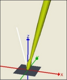
After interpolating, the BSDF data for incidence angle 15° appears and is properly oriented.
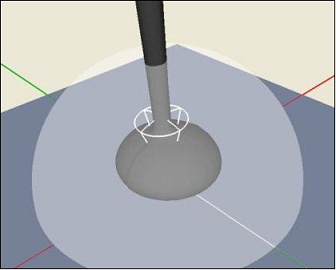
In addition to the BSDF interpolation done with the BSDF viewer, you can help Speos to distinguish specular and diffuse components. Specular and diffuse components are managed with different algorithms to speed up simulations.
A white wireframe cone is used to distinguish the specular part (shown inside the cone) from the diffuse part (shown outside the cone).
 |