


DOE and Thin Lens Surface Overview
Diffractive Surface
With diffractive surface, you can model thin lens that corresponds to a theoretical lens.
Two possibilities are available: Thin lens or Diffractive optical element (DOE).
For the diffractive optical element, this surface type models the DOE effect on light.
The example of a lens with a DOE on one of its face is used industrially in CD reader devices. With this you can have a simple optical system to make little focus point. The advantages are a simple mechanical structure, a low weight and a low price.
The DOEs can be used to focus on something else than a point: an ellipse for example. It is possible to replace a parabolic mirror by a plane DOE. It is possible to replace a complex optical element by a plane DOE with the right function.
Transmission
Basic Fresnel interactions for transmission trough a surface gives the following changes on photons direction (in the local surface’s base). 
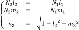
Ni |
Material index |
(li,mi,ni) |
Direction vector of the ray |
This direction change is modified as follows by a DOE surface:
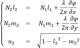
Where f is the user defined phase function:
lo |
The base wavelength at which the DOE has been designed |
f |
The diffractive focal of the DOE (at lo) |
r² |
x² + y² |
bi |
The radial coefficients of the polynomial |
P(x,y) |
The whole polygon (not with only radial coefficients) |
For a reflection
Equations are:

The surface is 100% transmitting or 100% reflecting.
If all coefficients are null, the surface acts as 100% specular simple scattering surface with reflection or transmission only.
Thin lens
With Thin lens you can focus a collimated beam without modeling a real lens.
Using DOE on a Thin Lens
We can use the DOE surface model on one plane face of a lens as follows:
Define a lens (with default parameters for example).
Define a box with x=50 y=50 z=10 dimensions and DOE surface defined in the previous EDIT box.
Make a Boolean operation: lens-box.
You can also create a source and watch the effect of the surface on light:
Without DOE

With DOE
This test shows that DOE surface model can be applied on lenses with a diffractive optical element on one of its faces only.
It is possible to test some coefficients because of their simple effect:
We can use l = 532 nm as the base wavelength and f = 10 mm for the diffractive focal.
We can see that a DOE with all its bi and aij coefficients null has no effect on light.
We can now let b1 = -0.5 and see that a collimated beam converges on one point located 10 mm from the DOE. If b1 = 0.5 the beam diverges.
The aij coefficients are used to break the revolution symmetry:
If b1 = -0.5, use a10 and a01 to move the focal point in the I and/or J vectors direction.
If a10=d / f the focal point moves d millimeters away.
The a20 and a02 coefficients allows you to use different focal lengths on x and y-axes: -0.05 for a 10 mm length.
Thin Lens Behavior
During a raytracing simulation, for each new ray impact, the optical lens center is computed by evaluating the intersection between the optical axis and the lens plan place at ray's impact. Then the impact coordinate from the optical lens center is used for computing the emergent ray direction.
_Thin_Lens_Representation.png)
- In Speos, the Thin Lens (*.doe) property is applied only on a flat face.
- The flat face (plane) is collinear to the lens plane defined by the thin lens vectors i and j.
Simple Lens
The setup for a simple lens is:
Select DOE surface.
Set the base wavelength.
Set the focal length of the lens.
Set all coefficients to zero, except B1 = -0.5.