


Contents of Ray Files
This page provides a description of ray files formats and contents. Ray files can be .ray, .txt or .tm25ray files.
.ray files
- N represents the ray index.
-
x, y, z represent the cardinal coordinates of the ray position.
x = X_start y = Y_start z = Z_Start
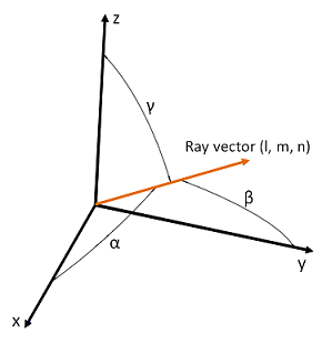
l, m, n represent the vector of the radiation direction expressed as cosines vector and the emission direction of the ray.
Cosines vector is: l = cos α m = cos β n = cos γ
 The following formula can be used (θ is the zenith angle, φ is the azimuth angle, el is elevation, az is azimuth):
- l = sin(θ) * cos(φ) = cos(el) * cos(az)
- m = sin(θ) * sin(φ) = cos(el) * sin(az)
- n = cos(θ) = sin(el)
Lambda represents the wavelength of the ray in nm.
Once you changed the spectrum, all the existing wavelengths are replaced by a random wavelength, chosen in the selected spectrum.
E represents the wavelength relative radiometric energy. Its weight is comprised between 0 and 1.
E is a constant value, that stay unchanged
when you edit or replace the spectrum. 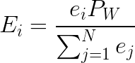 i is the ray index. Ei: flux in Watts of the propagated ray. ei: its relative flux as displayed in the ray editor. Pw: the total flux in Watts of the ray file. N: the
ray count (number of rays propagated in the simulation, which can be lower than the
number of rays in the ray file). The absolute power of each ray launched is calculated
at the end of the simulation.
i is the ray index. Ei: flux in Watts of the propagated ray. ei: its relative flux as displayed in the ray editor. Pw: the total flux in Watts of the ray file. N: the
ray count (number of rays propagated in the simulation, which can be lower than the
number of rays in the ray file). The absolute power of each ray launched is calculated
at the end of the simulation.
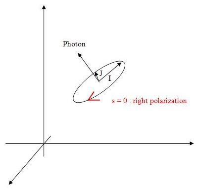
When the ray file type selected in the parameters of a sensor is Speos with polarization, then, its data is as following:
I: ellipse big axis normalized vector (o, p, q) 3 float ( such as o*o+p*p+q*q=1 )
r: equal to J / I (small axis divided by big axis) 1 float ( 0 <= r <= 1 )
s: right or left polarization 1 float ( 0:right or 1:left )
In Speos Standalone, when For ray file analysis option is checked in the Ray File Analysis, in General preferences:
nRs is the number of specular Reflections.
nRd is the number of diffuse Reflections.
nTs is the number of specular Transmissions.
nTd is the number of diffuse Transmissions.
.txt files
Two types of text formats are available to describe a .ray file. Here are their respective descriptions:
- SPEOS without polarization
Format Description
Example The first line of the file describes the number of rays
Then there is one line per ray. On every line, a ray is described following this pattern: N, x, y, z, l, m, n, w, e
5
1 -0.5 0.4 0.4 0.5 -0.1 0.7 555 1
2 0.7 -0.5 12 0.2 -0.4 0.2 555 1
3 0.8 -0.2 18 -0.5 -0.4 0.7 532 1
4 -0.1 0.5 4 0.5 0.2 0.7 452 1
5 1.7 -0.8 2 0.2 -0.4 0.6 633 1
- SPEOS with polarization
Format Description
Example The first line of the file describes the number of rays
Then there is one line per ray. On every line, a ray is described following this pattern: N, x, y, z, l, m, n, w, e, o, p, q, r, s
5
1 -0.52628386 -0.00855768 0.00000000 0.52024770 0.34379616 (...)
2 -0.86585391 -0.44513318 0.00000000 0.08552492 0.94339383 (...)
3 0.02308984 -0.88153327 0.00000000 -0.62660795 -0.27433285 (...)
4 0.34004232 0.50223148 0.00000000 0.62604368 -0.33856606 (...)
5 -1.62039423 3.59091830 110.00000000 -0.03101333 0.30122653 (...)
.tm25ray files
This standard has variants:
with or without spectrums,
with or without wavelengths.
Regarding output files generated by Speos such as simulations, Irradiance and 3D Irradiance sensors:
only one format,
one wavelength per ray (refer to Spectral Data Identifier 2),
polarization is always saved
Total Luminous Flux and Total Radiant Flux are always saved.
Regarding input files like sources, all variants are supported.
By clicking Edit ray file properties
 , you can edit the
properties of the .tm25ray file.
, you can edit the
properties of the .tm25ray file. .tm25ray files are based on the IES TM-25-13 standard.
TM-25 Ray File Properties
_Viewer_TM25_RayFile_Properties.png)
File Header Block
- Version: year of the file version
-
Creation Method: Identification of whether the file was created via
measurement or simulation using the following flags:
- 0 - Simulation
- 1 - Measurement
- Ray Start Position: Reference to how the initial ray emission points were
determined based on the following flags:
- 0 – Unknown / Undefined
- 1 – User
- 2 – Plane
- 3 – Sphere
- 4 – Cylinder
- 5 - Cuboid
- 6 – Geometry
- 7 – Back Propagated
- Spectral Data Identifier: Reference to the manner in which spectral data is
used in this file:
- 0 – No Wavelength Information
- 1 – Single Wavelength for all rays
- 2 – Wavelength defined per ray
- 3 – Single Spectrum for all rays
- 4 – Spectrum defined per ray
- Number of Spectral Tables: Quantity of spectral tables that will be presented in Spectral Tables Block.
- Number of Additional Ray Data Items: Quantity of additional data items that will be presented for each ray in Additional User Defined Data
Known Data Flags Block
Radiant Flux Definition: As defined in ANSI/IES RP-16-10, the time rate of flow of radiant energy, expressed in Watts.
Radiant Flux Flag: defines if data are present in the ray data line (0: Absent 1: Present (adds 1 value to the ray data line))
- Wavelength Flag: defines if data are present in the ray data line (0: Absent 1: Present (adds 1 value to the ray data line))
Luminous Flux Definition: As defined in ANSI/IES RP 16-10, luminous flux is obtained from spectral radiant flux ϕλ, the spectral luminous efficiency V(λ) and the maximum spectral luminous efficacy Km = 683 lm/W by integration: ϕv = Km ∫ ϕλ(λ) V(λ) dλ.
Luminous Flux Flag: defines if data are present in the ray data line (0: Absent 1: Present (adds 1 values to the ray data line))
Stokes Parameters Definition: Four certain numbers S0, S1, S2, and S3 are used to describe the polarization state of electromagnetic radiation along a ray, as defined in standard text books on electromagnetic radiation. They form a four-dimensional vector (S0,S1,S2,S3), called the Stokes vector. S0 is defined as the total radiant flux, S1 and S2 describe the amount and orientation of linear polarization, while S3 describes the amount and orientation of circular polarization.
Stokes Flag: defines if data are present in the ray data line (0: Absent 1: Present (adds 6 values to the ray data line))
Tristimulus Definition: As defined in ANSI/IES RP-16-10, this corresponds to the amounts of each of three specific primaries to match the color of the light. The actual values are obtained by integration of spectral radiant flux using the three color matching functions defined by the Commission Internationale de l’Eclairage.
Tristimulus Flag: defines if data are present in the ray data line (0: Absent 1: Present (adds 2 values to the ray data line))
Spectrum Index Definition: index to the spectrum to be used for this ray from the spectrum tables.
Spectrum Index Flag: defines if data are present in the ray data line (0: Absent 1: Present (adds 1 values to the ray data line))
Description Header Block
- Name of Light Source: Name of the light source that the ray file describes
- Manufacturer of Light Source: Name of the manufacturer of the light source
- Creator of Optical Light Source Model: Name of the creator of the light source model used to generate the ray file. (may also be the creator of the CAD geometry used to simulate the ray data or the name of the technician measuring the ray data)
- Creator of the Ray File: Name of the company creating the ray file
- Measurement Equipment / Simulation Software: Name and description of the measurement equipment or the simulation software used to gather or generate the ray data
- Camera Information: Name and a description of the camera used for the measurement equipment.
- Light Source Operation Information: Additional information about the light source that may be relevant to a user of the ray data
- Additional Information: Additional information about the ray file that may be relevant
- Data Reference to Light Source Geometry: Description of how the origin point in the ray data aligns with some point on the light source.