


Raw Time of Flight
This page provides more information on the Raw Time of Flight (*.OPTTimeOfFlight) file and describes how to operate/analyze its content.
Description
The *.OPTTimeofFlight is a result file of a LiDAR simulation used to store the raw time of flight of each pixel of the LiDAR sensor.
You can use this file to read and export specific data or post-treat it to output results, like a 3D representation of the scene in the form of a point cloud (impacts collected during simulation).
This file is a compressed binary file that can store large amounts of data but that can only be accessed through APIs.
Principle
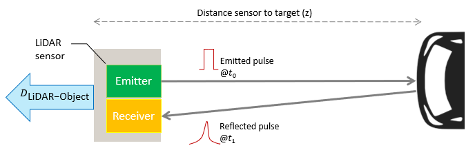
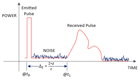
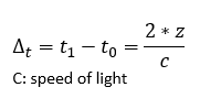
The Raw Time of Flight essentially represents the temporal power of a pixel expressed in Watts. It describes the time interval between the emission of the light pulse and its detection after being reflected by an object in the scene. Then, through data conversion, the LiDAR-to-object distance is derived from this time of flight.
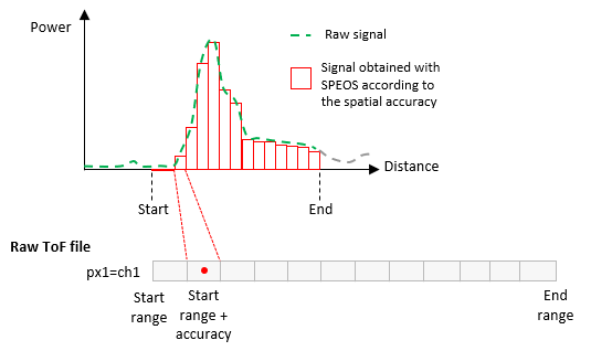
In Speos, the raw time of flight data correspond to the optical power integrated in the pixel for a given distance. This distance depends on the Spatial accuracy of the sensor, that is its discrimination step between two measurement points (in mm).
Data Storage
Number of rotations * Number of scans * Number of time of flight samples * 8 bytes
With Number of time of flight samples = (End range - Start range) / Spatial accuracy
- Generic information (often related to input parameters): sensor pixels' number and size, sensor min and max detection range, spatial accuracy, number of channels, source and sensor origins and orientation etc.
- Channels (corresponding to beams) with the different time of flight data comprising the power, line of sight directions and detection range.
- Static LiDAR sensor generates one channel.
- Scanning LiDAR sensor generates one channel per scan configuration.
- Rotating LiDAR sensor generates one channel per rotation configuration, per scan configuration.
- the unique channel of the Static LiDAR sensor contains a number of sub-channels that corresponds to its resolution.
- each channel of a Scanning / Rotating LiDAR sensor with no resolution contains one sub-channel.
- each channel of a Scanning / Rotating LiDAR sensor with a resolution contains a number of sub-channels that corresponds to its resolution.
To extract or post process the raw data stored in the compressed binary file, you must parse the result file using scripts and dedicated APIs.