


Standard Sharp Cutoff Beam Parameters
This page describes the parameters used to create a Sharp Cutoff beam in standard mode.
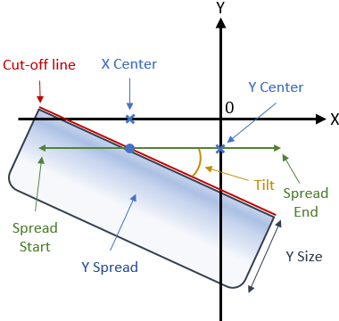
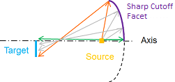
Cut-off line points' coordinates
To place the cut-off line on the target, two coordinates must be created. These coordinates (X and Y centers) are used to determine the top borderline of the beam on the target.
- X center: X coordinate of the point used to place the cut-off line on the target.
- Y center: Y coordinate of the point used to place the cut-off line on the target.
Cut-off line amplitude
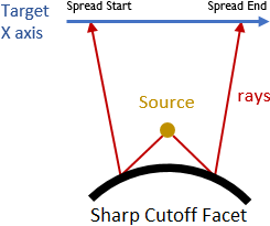
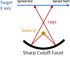
The beam's amplitude is defined along X axis and determines the emission pattern of the beam (that is, if the beam has a narrow or broad emission).
- Spread start: Length between the middle point of the specification line and its left extremity.
- Spread end: Length between the middle point of the specification line and its right extremity.
- When Spread start < Spread end, the rays never cross each other. The Sharp Cutoff element is convex in X direction.
- When Spread start > Spread end, the rays cross each other. The Sharp Cutoff element is concave in X direction.Note: Convex and Concave parameters have no impact on the rays direction on the Target X axis.
 |
 |
| Spread Start < Spread End | Spread Start > Spread End |
Cut-off line orientation
The orientation of the cut-off line is controlled by the tilt angle.
Tilt: Angle between X target axis and the specification line.
Light distribution under the cut-off line
- Y size: Beam spread along Y target.
- Y spread: Ratio driving the beam spread along Y target axis.Note: When the ratio equals 100%, the light distribution inside the specification line tends to be uniform. The less the ratio is, the less spread/the more concentrated the beam light will be under the specification line.
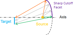
Elements shape
The convexity/concavity of the elements determine the behavior of the rays on the target.
Note: The facets of the reflector will not necessarily appear concave or convex.
- Convex: a ray reflected on the top of the element will come to the top of the target when Y size is non-null. Rays never cross each other.
- Concave: a ray reflected on the top of the element will come to the bottom of the target when Y size is non-null. Rays cross each other.
 |
 |
| Beam ray tracing of a sharp cutoff element and a non-null Y Size - Convex on the left, Concave on the right | |
Performance
A progress bar displays the progress of the feature generation algorithm. The displayed information are:
- Element Numbers: Current and total elements of the feature.
- Status: Progress on the feature generation algorithm (percent).
- Estimated time remaining: Remaining time for the feature generation algorithm (seconds).