


Honeycomb
The grid determines the size and distribution of the lenses over the support.
By default, elements are distributed onto the support according to a rectangular pattern. This distribution can be customized as well as the shape and size of the lens itself.
Axis System
An axis system is required to define the element's orientation and projection on the support.
This axis system is, by default, inherited from the source definition.
Note: If you define manually one axis only, the other axis is
automatically (and randomly) calculated by Speos in the 3D view. However, the other axis in the
Definition panel may not correspond to the axis in the 3D view. Please refer to the axis in the 3D
view.
Definition
From the definition section you can:
- Define how the elements are going to be distributed on the support by setting start and end values for X and Y axes.
- Apply a rotation to the lenses (the X axis is taken as a reference to apply the rotation to the elements).
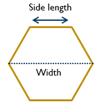
- Adjust the dimensions of the lenses by adjusting either their width or side length.
From the specification tree, under the feature node, more parameters are available to customize the pattern distribution:
- X Start: Start value for the feature size along X Grid (mm).
- X End: End value for the feature size along X Grid (mm).
- Y Start: Start value for the feature size along Y Grid (mm).
- Y End: End value for the feature size along Y Grid (mm).
- X Count: Number of elements along X Grid.
- Y Count: Number of elements along Y Grid.
- Rotation: Rotation of elements along X axis (deg).
- Side Length: Size of the hexagons' side (mm).
- Width: Hexagons' width (mm).