Creating the UV Mapping
This page describes the first steps of a texture mapping creation, that is the definition of the UV mapping of geometries on which texture is applied.
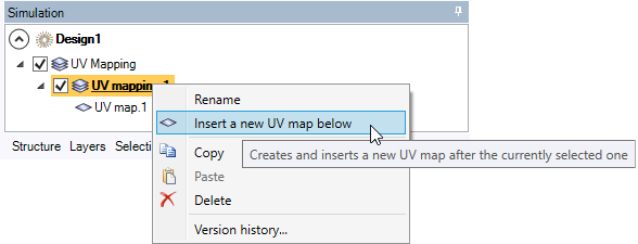
To create a UV Mapping:
-
From the Light Simulation tab, click UV Mapping
_UV_Mapping.png) .
.
-
In the 3D view, click
_Simulation_Selection_Geometry.png) , select the geometries on which to apply the current mapping and click
, select the geometries on which to apply the current mapping and click _Validation.png) to validate.
to validate.
During UV Mapping edition, the texture set or the checker texture is displayed in the 3D view on the associated geometries and is updated upon modifications.
Tip: If you need a certain mapping type (a planar mapping for example) for several geometries, select them all and create only one UV mapping that will be used for each geometry. -
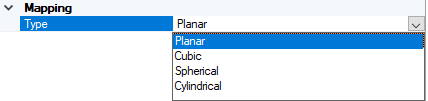
In the first UV map, select the mapping type you need.
-
Planar
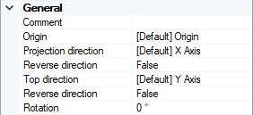
- Define the Axis System of the Planar mapping type:
- For Origin, click
_Origin_Point.png) and select the middle point of the image texture you want to apply.
and select the middle point of the image texture you want to apply. - For Projection direction, click
_Projection_Axis.png) and select a line defining the direction in which the image texture should be projected on the plane.
and select a line defining the direction in which the image texture should be projected on the plane. -
For Top direction, click
_UV_Mapping_Top_Direction.png) and select a line defining the orientation of the image texture on the plane.Note: If you define manually one axis only, the other axis is automatically (and randomly) calculated by Speos in the 3D view. However, the other axis in the Definition panel may not correspond to the axis in the 3D view. Please refer to the axis in the 3D view.
and select a line defining the orientation of the image texture on the plane.Note: If you define manually one axis only, the other axis is automatically (and randomly) calculated by Speos in the 3D view. However, the other axis in the Definition panel may not correspond to the axis in the 3D view. Please refer to the axis in the 3D view. - or click
_Axis_System_Autofill.png) and select a coordinate
system to autofill the Axis System.
and select a coordinate
system to autofill the Axis System.
- For Origin, click
- If you want to apply a rotation to the current image, define a rotation value in degrees.
- Define the Axis System of the Planar mapping type:
-
Cubic
- Define the Axis System of the Planar mapping type:
- For Origin, click and select the middle point of the image texture you want to apply.
- For Projection direction, click and select a line defining the direction in which the image should be projected on the plane.
-
For Top direction, click
and select a line defining the orientation of the image texture on the plane.Note: If you define manually one axis only, the other axis is automatically (and randomly) calculated by Speos in the 3D view. However, the other axis in the Definition panel may not correspond to the axis in the 3D view. Please refer to the axis in the 3D view. - or click and select a coordinate
system to autofill the Axis System.
- For Origin, click
- If you want to apply a rotation to the current image, define a rotation value in degrees.
- Define the Axis System of the Planar mapping type:
-
Spherical
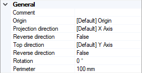
- Define the Axis System of the Planar mapping type:
- For Origin, click and select a point placed in the center of the sphere.
- For Projection direction, click and select a line defining the direction in which the texture should be projected.
-
For Top direction, click
and select a line defining the orientation of the image texture on the plane.Note: If you define manually one axis only, the other axis is automatically (and randomly) calculated by Speos in the 3D view. However, the other axis in the Definition panel may not correspond to the axis in the 3D view. Please refer to the axis in the 3D view. - or click and select a coordinate
system to autofill the Axis System.
- For Origin, click
- If you want to apply a rotation to the texture, define a rotation value in degrees.
-
In Perimeter, define the perimeter of the sphere in mm.
Tip: If the geometry was build with SpaceClaim modeler, you can obtain the perimeter by clicking Measure_Measure.png) and clicking on the geometry.
and clicking on the geometry.
- Define the Axis System of the Planar mapping type:
-
Cylindrical
- Define the Axis System of the Planar mapping type:
- For Origin, click and select the point on the revolution axis of the cylinder.
- For Projection direction, click and select a line defining the direction in which the texture should be projected.
-
For Top direction, click
and select a line defining the orientation of the image texture on the plane.Note: If you define manually one axis only, the other axis is automatically (and randomly) calculated by Speos in the 3D view. However, the other axis in the Definition panel may not correspond to the axis in the 3D view. Please refer to the axis in the 3D view. - or click and select a coordinate
system to autofill the Axis System.
- For Origin, click
- If you want to apply a rotation to the texture, define a rotation value in degrees.
-
In Perimeter, define the perimeter of the cylinder basis in mm.
Tip: If the geometry was build with SpaceClaim modeler, you can obtain the perimeter by clicking Measure and clicking on the geometry.
CAUTION: When a cylindrical mapping is applied on a cylindrical geometry, the preview of the texture mapping may be inconsistent. To avoid such an issue:- Open the Properties of the body.
- Set Tessalation Quality Level to Custom.
- Set Max edge length to a value consistent with the body size.
_UV_Mapping_Issue_Cylindrical.png)
- Define the Axis System of the Planar mapping type:
-
-
In U and V sections, respectively denoting the horizontal and vertical axes of the mapping projection:
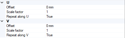
-
If you selected a set of geometries that require different mapping applications: