


Creating a LiDAR Simulation
Creating a LiDAR simulation allows you to generate output data and files that enable to analyze a LiDAR system and configuration. The LiDAR simulation supports several sensors at a time.
To create a LiDAR Simulation:
A sensor and source must already be created.
- From the Light Simulation tab, click
_Simulation_Lidar.png) .
.
-
In the 3D view click
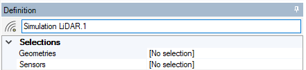
_Simulation_Selection_Geometry.png) to select the geometries for which you want to calculate the distance to the Lidar.
to select the geometries for which you want to calculate the distance to the Lidar.Your selection appears in the Geometries list.
Tip: You can select elements from the 3D view or directly from the tree.To deselect an element, click back on it.
To rapidly select all the faces of a same element, click one face of this element and press CTRL+A.
-
In the 3D view click
_Simulation_Selection_Sensor.png) and from the tree select the previously created LiDAR sensor(s).
and from the tree select the previously created LiDAR sensor(s).Your selection appears in the Sensors list.
Note: When selecting several sensors in one LiDAR simulation, the sensors do not illuminate each other and their contributions are not merged. The simulation will produce individual results for each sensor selected. Define the criteria to reach for the simulation to end:
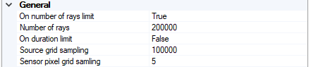
- To stop the simulation after a certain number of rays were sent, set On number of rays limit to True and define the number of rays. The number can be larger than 2 Giga rays.
-
If you are working with static LiDARs and want to stop the simulation after a certain duration, set On duration limit to True and define a duration.
Note: If you activate both criteria, the first condition reached ends the simulation.If you select none of the criteria, the simulation ends when you stop the process.
- In Source grid sampling, define the number of samples used to calculate the field of views.
- In Sensor pixel grid sampling, define the number of samples used along each pixel side to calculate the field of views.
-
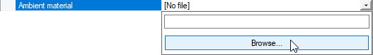
In Ambient material, browse a .material file if you want to define the environment in which the light will propagate (water, fog, smoke etc.).
The ambient material allows you to specify the media that surrounds the optical system. Including an ambient material in a simulation brings realism to the optical result.
The .material file is taken into account for simulation.
 Note: If you do not have the .material file corresponding to the media you want to use for simulation, use the User Material Editor, then load it in the simulation.
 -
If you want to consider time during the simulation, set Timeline to True.
Note: This allows dynamic objects, such as Speos Light Box Import and Scanning or Rotating LiDAR Sensors, to move along their defined trajectories and consider different frames corresponding to the positions and orientations of these objects in simulation.Note: For more information on Timeline, refer to Understand LiDAR Simulation with Timeline. - From the Results section, filter the results you want to generate by setting
them to True or False: Note: The Fields of view and Map of depth result types are only available for static LiDARs.
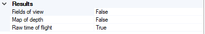
- If you want a visualization of the source, sensor and LiDAR fields of view to be displayed in the 3D view after simulation, activate Fields of view.
- If you want a map of depth to be generated after simulation, activate the corresponding option.
If you want to generate a Raw time of flight (*.OPTTimeOfFlight) result file, activate the corresponding option.
Note: If you need more information about grid sampling or results, see Understanding LIDAR Simulation Results. If Timeline is set to True, from the Timeline section, define the Start and End times.
_Lidar_Timeline.png) Warning: From the version 2022 R2, the Timeline Start and End parameters have been improved in order to enter time values below 1ms. This change will impact your custom scripts, and will need to be modified consequently, as previous time format is no longer supported.
Warning: From the version 2022 R2, the Timeline Start and End parameters have been improved in order to enter time values below 1ms. This change will impact your custom scripts, and will need to be modified consequently, as previous time format is no longer supported.- In the 3D view, click Compute
_Compute.png) to launch the simulation.
to launch the simulation.
The simulation is created and results appear both in the tree and in the 3D view.
If Timeline is activated, the Raw time of flight simulation result will contain all the timestamps of the simulation.
When running a Rotating LiDAR Simulation with Speos HPC Compute, each thread sends one ray per pulse.