


Creating a Direct Simulation
The Direct Simulation is commonly used to analyze standard optical systems.
To create a Direct Simulation:
Make sure the Speos inputs used to define the Simulation (example: sources, geometry, sensors) are located in the same component as the simulation, or in a child component.
-
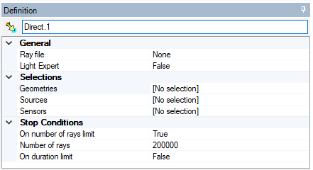
From the Light Simulation tab, click Direct
_Simulation_Direct.png) .
.
-
If you want a ray file to be generated at the end of the simulation, from the Ray File drop-down list:
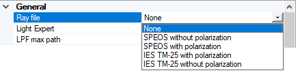
- Select SPEOS without polarization to generate a ray file without polarization data.
- Select SPEOS with polarization to generate a ray file with the polarization data for each ray.
- Select IES TM-25 with polarization to generate a .tm25ray file with polarization data for each ray.
Select IES TM-25 without polarization to generate a .tm25ray file without polarization data.
Note: The size of a ray file approximates 30Mb to 1 Mrays. Consider freeing space on your computer prior to launching the simulation.CAUTION: If the surface that will be used for the creation of the ray file is fully absorbent (SOP set to Mirror 0%), all rays are absorbed and no ray will be integrated in the ray file. This ray file will be empty.
- If you want the simulation to generate a Light Path Finder file, set Light Expert to True.
If you activated Light Expert, in LPF max path, you can adjust the maximum number of rays the light expert file can contain.
Note: The default value is 1e6 (1 million rays).
For more information on Light Expert analyses, refer to Light Expert.
-
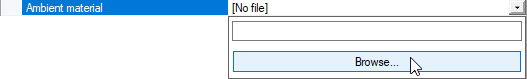
In Ambient material, browse a .material file if you want to define the environment in which the light will propagate (water, fog, smoke etc.).
The ambient material allows you to specify the media that surrounds the optical system. Including an ambient material in a simulation brings realism to the optical result.
The .material file is taken into account for simulation.
 Note: If you do not have the .material file corresponding to the media you want to use for simulation, use the User Material Editor, then load it in the simulation.
 -
In the 3D view, click
_Simulation_Selection_Geometry.png) to select geometries,
to select geometries, _Simulation_Selection_Source.png) to
select sources and
to
select sources and _Simulation_Selection_Sensor.png) to
select sensors.
to
select sensors.The selected geometry, source(s) and sensor(s) appear in their respective lists as Linked objects.
- If Light Expert is activated, the LXP check box is automatically activated for all compatible sensors whether the sensor is already listed or added afterwards. If you do not want LXP activated for a sensor, uncheck LXP for the sensor.
_Simulation_LXP_Check.png)
In case you add a Light Expert Group for a multi-sensors light expert analysis, the LXP is automatically activated.
-
Define the criteria to reach for the simulation to end:
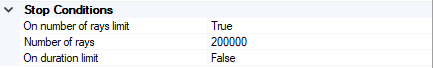
- To stop the simulation after a certain number of rays were sent, set On number of rays limit to True and define the number of rays.
-
To stop the simulation after a certain duration, set On duration limit to True and define a duration.
Note: If you activate both criteria, the first condition reached ends the simulation.If you select none of the criteria, the simulation ends when you stop the process.
Note: If you want to adjust the Direct Simulation advanced settings, see Adjusting Direct Simulation settings.
Preview the Meshing of the geometries before running a simulation and adjust meshing values if needed to avoid simulation or geometries errors.
- In the 3D view, click Compute
_Compute.png) to launch the simulation.
to launch the simulation.
.
To compute the simulation in progressive rendering, click Preview
_Simulation_Preview.png) . This option opens a new window and
displays the result as the simulation is running.
. This option opens a new window and
displays the result as the simulation is running.
Preview is compatible with NVIDIA GPUs only. GPUs supported are NVIDIA A5000 or higher.
The Direct Simulation is created along with .xmp results, an HTML report and if Light Expert is activated, a .lpf file. The .xmp result also appears in the 3D view on the sensor(s).
In case of a Light Field Source used, an Optical Light Field *.olf file is generated.
If only a Natural Light Ambient Source is used in the Direct Simulation, no power will be noted in the HTML report, as no power is set in the definition of the Source (unlike other sources).