Note: For same values of meshing, meshing results can be
different between the CAD platforms in which Speos is integrated.
To define the Simulation Meshing:
The Simulation Meshing can be defined for Interactive, Direct, Inverse, LiDAR, Virtual BSDF Bench
Simulations, a Light Box Export, and an Optical Design Exchange feature.
-
From the Simulation tree, right-click the feature and select
Options
_Speos_Options.png) .
.
_Simulation_Settings_Meshing_01.png)
-
From the Sag Mode drop-down list:
- Select Proportional to Face size to create a mesh of triangles that
are proportional to the size of each face of the object. The sag and step value therefore depend
on the size of each face.
- Select Proportional to Body size to create a mesh of triangles that
are proportional to the size of the object. The sag and step value therefore depend on the size of
the body.
- Select Fixed to create a meshing regardless of the size of the body
or faces.
Note: We recommend you to apply the same mode for both Sag and Step.
-
In Sag Value, define the maximum distance between a segment and the object
to mesh.
-
From the Step Mode drop-down list:
- Select Proportional to Face size to create a mesh of triangles that
are proportional to the size of each face of the object. The sag and step value therefore depend
on the size of each face.
- Select Proportional to Body size to create a mesh of triangles that
are proportional to the size of the object.
- Select Fixed to create a mesh of triangles fixed in size regardless
of the size of the body.
Note: We recommend you to apply the same mode for both Sag and Step.
-
In Step Value, define the maximum size of a meshing triangle
segment.
-
In Angle, define the maximum angle allowed between the normals of two
adjacent mesh triangles.
-
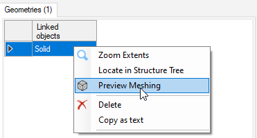
If you want to display the current meshing properties in the 3D view, from the
Geometries list, right-click the geometry and click Preview
Meshing.
The meshing is defined and applied to the geometries linked to the
feature.