


Draw (surface properties)
The settings for how surfaces are drawn are selected in the Draw section of the Surface Properties window. The Surface Properties can be reached by clicking the down arrow in the Surface Properties bar above the Lens Data Editor.
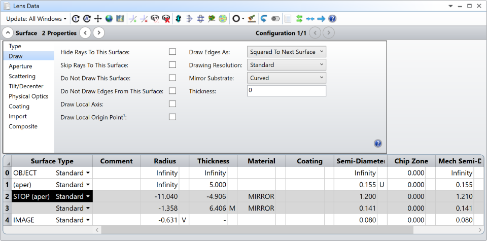
Hide Rays To This Surface
If checked, no rays will be drawn to the surface in the various types of layout plots. See Skip Rays below for an alternate means of hiding rays to dummy surfaces.
Skip Rays To This Surface
If checked, rays will skip the surface. This means ray segments will be drawn from the last surface that was not a coordinate break and did not have the Skip Rays option checked, all the way to the next surface that is not a coordinate break and does not have the Skip Rays option checked. For example, if Skip Rays is selected on surfaces 3, 4, and 5, rays will be drawn directly from the coordinates on surface 2 to their coordinates on surface 6, as long as surfaces 2 and 6 are not coordinate breaks.
The purpose of the Skip Rays option is to suppress the drawing of rays to and from dummy surfaces. Although this can be useful in some cases, this option can cause strange, misleading layout plots if the skipped surfaces can refract or diffract the rays. Therefore, the option should only be used on dummy (optically ineffective) surfaces. OpticStudio does not check or verify that surfaces with the Skip Rays option are in fact dummy surfaces, so care is required when using this feature.
Do Not Draw This Surface
If checked, the surface will not be drawn on layout plots.
Do Not Draw Edges From This Surface
If this option is checked, then no edges will be drawn from this surface to the next surface. This feature makes for cleaner drawings in some systems, especially those using liquids or other non-air fillers between optical surfaces.
Draw Local Axis
If checked, an arrow will be drawn to indicate the orientation of the local Z axis at the surface on 3D Layout plots. The size of the arrow is determined by the fletch size, see " Fletch Size ".
Draw Local Origin Point
If checked, a sphere will be drawn to indicate the local origin position in 3D Layout and Shaded Model plots. The size of the sphere is determined by the Points control under the Line Thickness settings in the toolbar of the plot window. It rescales with the zoom so that it always appears with a similar size on the screen. The color will be similar to the surface color by default. The dropdown that appears once the check box is checked allows for the selection of different colors.
Draw Edges As
This setting controls how edges that connect a surface to the next surface are drawn on the various layout and element drawings. Usually this setting is only used to connect edges on surfaces with circular apertures defined by the radial clear semi-diameter or semi-diameter. Other cases may use another, usually simpler algorithm than the options described here, or may not draw the edge at all. The available options are described below:
Squared To Next Surface A flat face is drawn radially outward from the smaller of the current and next surfaces to match the clear semi-diameter or semi-diameter of the larger surface. The outer edge of the surface is then formed by a cylinder extending to connect the surface edges.
Tapered To Next Surface The current and next surface are connected by a single tapered cylinder.
Flat To Next Surface The current surface edge is drawn as a cylinder at the current clear semi-diameter or semi-diameter value extending to the contact point on the next surface.
The 3D Layout, Wireframe, Shaded Model, and Solid Model plots currently do not support the "Flat To Next Surface" option. Surfaces with this setting selected will be drawn using the "Squared To Next Surface" method.
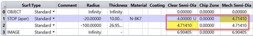
Below are three examples of these three drawing options for a simple singlet lens:
Option 1: Surface 1: Draw Edges as "Squared to Next Surface"

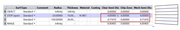
Option 2: Surface 1: Draw Edges as "Tapered to Next Surface"
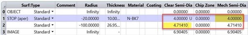
Option 3: Surface 1: Draw Edges as "Flat to Next Surface" (Note, this option is not drawn but is equivalent to the red dotted lines)

Drawing Resolution
This setting controls the resolution with which the surface is rendered in the layout and Shaded Model plots. Options are Standard, Medium, High and Presentation. Note that this setting is available for all surfaces, even in cases when it might not apply. Also, it may be that the setting from the front surface of a lens affects the back surface – or vice-versa – so it is recommended that the same setting be specified for both the front and back surfaces of a lens whenever possible.
Mirror Substrate and Thickness
Sequential surfaces with a glass type of "MIRROR" may be drawn as either a thin surface, or as a solid object with a substrate. The back of the substrate may be a flat surface that is perpendicular to the local z axis, or as a curved surface that follows the contour of the actual mirror surface. The thickness of the substrate is measured along the local z axis at the vertex of the surface, even if the surface aperture is decentered or user defined. OpticStudio will draw the edges of the substrate by connecting the mirror surface and the substrate back. All surface and aperture types are supported on all layout plots.
By default, OpticStudio will draw the back of the mirror substrate as a curved surface with a thickness of 4% of the surface clear semi-diameter or semi-diameter, or 0.5 lens units if the clear semi-diameter or semi-diameter is zero. The default thickness will be used if the Mirror Substrate Thickness parameter is set to zero.
Mirror substrates will not be drawn on surfaces which are mirrors in some, but not in all defined configurations. Likewise, they will not be drawn on mirrors that are only set to draw in specific configurations. Mirror substrates are also not drawn on surfaces which are Mangin mirrors (mirrors on the back of glass substrates) in any configuration. To draw mirror substrates on surfaces which are present in some configurations but not in others, use the multi-configuration operand IGNR to ignore the mirror surface rather than GLSS to change the surface from a mirror to glass or air. See "Adding and removing elements".
Next: