


Aperture (surface properties)
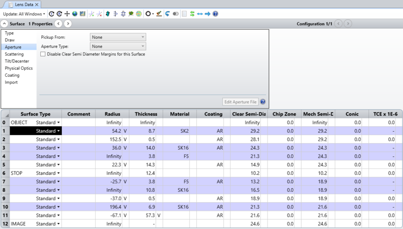
Setting aperture data for each surface is done in the Aperture section of the Surface Properties window. The Surface Properties can be reached by clicking the down arrow in the Surface Properties bar above the Lens Data Editor.
Surface apertures are used to account for the effects of vignetting. The aperture and obscuration types define regions which pass or stop rays, respectively. More than one aperture may be described at a given optical element by inserting a dummy surface with zero thickness at the desired location, and then setting additional apertures on that surface. This is useful for constructing complex apertures. Multiple simultaneous apertures and obscurations may also be defined on a single surface using the user defined apertures and obscurations feature, see "User defined apertures and obscurations".
Please note that, although this is allowed in Sequential Mode, it is not physically meaningful to define a surface aperture that extends beyond the clear semi-diameter or semi-diameter of the surface. For this reason, if the surface aperture extends over the defined clear semi-diameter or semi-diameter, it may not be drawn correctly in the system viewers.
Aperture Type
None When "None" is selected for the aperture type (the default), all rays which can be refracted or reflected by this surface are allowed to proceed. To clear any aperture to this default state, or to change the current aperture type, select another aperture type.
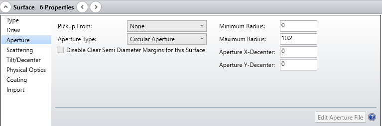
Circular Aperture/Obscuration A Circular Aperture defines an annular region which vignettes all rays which strike the surface inside of the minimum radius, and outside of the maximum radius. If the ray is between the minimum and maximum radii, then the ray will be allowed to proceed. The Circular Obscuration is the complement of the Circular Aperture.
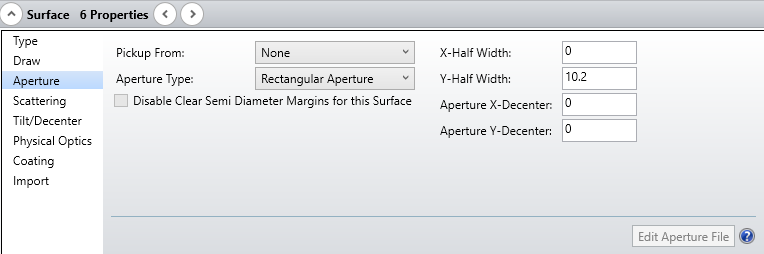
Rectangular Aperture/Obscuration Rays are vignetted which intercept the surface outside the rectangular region defined by the half widths in x and y. The Rectangular Obscuration is the complement to the Rectangular Aperture.
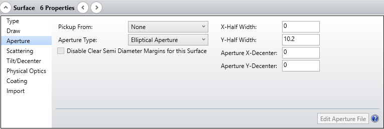
Elliptical Aperture/Obscuration Rays are vignetted which intercept the surface outside the elliptical region defined by the half widths in x and y. The Elliptical Obscuration is the complement to the Elliptical Aperture.
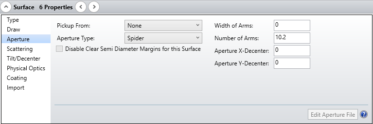
Spider The spider is defined by the width of each arm, and by the number of arms. OpticStudio assumes the arms are all the same width, and that they are spaced in equal radial angles. The first arm starts at a radial position of zero degrees, which is along the local positive x-axis. More complex spiders, which contain arms of different widths at unequal angles can be constructed using several spiders on adjacent dummy surfaces. The coordinate break surfaces can be used to rotate the spider(s) to any desired angle.
User Defined Aperture/Obscuration OpticStudio supports a general user specified aperture defined by a series of line segments, arcs, circles, polygons, and rectangles. The aperture may be closed in a simple or complex way, and multiple aperture regions may be defined which are either nested or not nested. To define a user defined aperture or obscuration, select the desired type (aperture or obscuration) from the list of aperture types. The "Aperture File" control will list all available user defined aperture (UDA) data files.
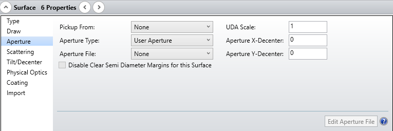
The UDA files are text files that may be created and edited using any text editor. The UDA files are stored in the <objects>\Apertures folder (see "Folders"). The button "Edit Aperture File" will invoke a text editor to allow user editing of the selected UDA file. The UDA file needs to saved and the lens file updated to make the changes effective. The UDA Scale is a dimensionless multiplier that scales the aperture defined in the UDA file. This control allows scaling of the UDA without need to modify the UDA file. See "User defined apertures and obscurations" in the next section.
Floating Aperture A floating aperture is very similar to the circular aperture, except the minimum radius is always zero, and the maximum radius is always equal to the clear semi-diameter or semi-diameter of the surface. Since the clear semi-diameter or semi-diameter value may be adjusted by OpticStudio (when in automatic mode) the aperture value "floats" as the clear semi-diameter or semi-diameter value. The floating aperture is useful when macros or external programs use OpticStudio to trace rays that may lie outside of the default clear semi-diameters or semi-diameters, and these rays are to be vignetted. Note that if a Surface Aperture is set to None and the surface is not a dummy surface, changing the Solve Type of Semi-Diameter or Clear Semi-Diameter on the surface from Automatic to Fixed will automatically change the Surface Aperture to Floating Aperture.
Aperture decenters and pickups
All types of apertures may be decentered from the current optical axis by specifying either X- or Y-decenters, or both. The decenters are given in lens units. If the identical aperture is used on more than one surface, the aperture "Pickup From" is a useful feature. Any aperture may be picked up from any previous surface.
Aperture projection on non-plane surfaces
All apertures are modeled as a surface projected from the vertex tangent plane onto the optical surface. The actual ray-surface x and y intercept coordinates are used to determine vignetting, the z coordinate is ignored. Different results may be calculated for steep optical surfaces if the aperture is placed on a dummy surface in front of the optic, instead of being directly entered on the curved surface. This will only occur if the ray incidence angles are steep. Usually it is best to place the apertures directly on the optical surface, unless of course the dummy surface more accurately represents the situation.
Next: