


User Defined
The user defined surface (UDS) is a powerful, flexible, and fast way of implementing surfaces not already built into OpticStudio. A UDS may be any shape, have any refractive, reflective, or diffractive properties, may impart any arbitrary phase to the beam, and may be followed by either homogeneous media or by a gradient index media of arbitrary form. A UDS may also apodize or attenuate the beam arbitrarily, or be used to define any electric field or coating data for polarization analysis. This latter capability allows the beam to be partially transmitted according to an arbitrary formula or table as defined by the user at any surface in the optical system.
The secret to this great flexibility is that all the properties of the surface are defined by the user in a separate C or C++ program compiled and linked into OpticStudio dynamically using the Windows Dynamic Link Library (DLL) capability. The DLL must contain functions which return to OpticStudio all the data required to draw the surface, trace rays, compute refraction angles, and for gradient index, to determine the index as a function of position within the media following the surface.
Because the DLL is compiled code, and because OpticStudio passes to the DLL a pointer to the data that needs to be computed, UDS are very fast; nearly as fast as native OpticStudio code (there is a small amount of overhead due to the function call).
The power of the UDS comes at a price, although it is a reasonable one. Use of the UDS does require that the user have a suitable compiler or development tool that can generate 32 bit (or 64 bit if using the 64 bit version of OpticStudio) Windows compatible DLLs. It is also assumed that the user can write the required code, and most importantly, ensure that the code is reliable and bug-free. To maximize speed, OpticStudio performs very little error checking on data returned by the DLL, and so buggy UDS DLLs are quite capable of bringing OpticStudio to a crash.
For this reason, technical support on the implementation of UDS is strictly limited to illustrating that the provided sample files work correctly.
The UDS DLL
The best way to learn how to create a UDS DLL is to start by copying the source code file (the one that ends in .C) of a sample DLL to a new file name, edit the sample to suit your requirements, and then recompile to make a new DLL. A good portion of the DLL source code is "boiler plate" which is common to all DLLs.
There are two files that are required to define a UDS DLL: a C (or C++) source code file such as MY_SURF.C, and a header file called USERSURF.H. Only the C file needs to be modified. The C file defines 2 functions; the first is "DLLMain" which is used to (optionally) initialize data used by the DLL. The other function is "UserDefinedSurface5", and this is the function that is modified for each surface type. Earlier versions of the OpticStudio User Defined surface interface used the function names UserDefinedSurface, UserDefinedSurface2, UserDefinedSurface3 and UserDefinedSurface4; these names are still supported but are obsolete. New DLL files should use UserDefinedSurface5.
OpticStudio passes two structures to the function, and these structures are defined in the USERSURF.H file.The structures are:
- "USER_DATA"
- "FIXED_DATA5"
USER_DATA
That data structure contains:
- The ray x, y, z locations on a plane tangent to the surface vertex. The DLL must iterate to the real surface (or calculate intercept analytically) and return the updated ray location.
- l, m, n direction cosines of the ray at the ray intercept
- ln, mn, nn surface normal at the ray intercept to be computed and returned
- Other data like index for gradient index, transmission, path length
The DLL must compute all new ray data after interacting with surface.
FIXED_DATA5
This data structure mainly contains data the DLL cannot change like all surface data in the editors, ray wavelength, polarization state, ... . The ray polarization state and the scaling of parameters are the only data the DLL may modify
FIXED_DATA5 also contains a "Type" and "Numb" parameters indicating what data OpticStudio wants from a given call to the DLL. Inside the UserDefinedSurface5 function is a C "switch-case" construct on those parameters. "Type" is a number between 0 and 10, inclusive.
The "Type" codes are described in the following table:
| Type | What Zemax wants the DLL to compute |
| 0 | The Surface name, radial symmetry status, and grin status |
| 1 | The name of the parameter columns |
| 2 | The name of the extra data columns |
| 3 | The sag and alternate sag of the surface |
| 4 | A paraxial ray trace to and refraction through the surface |
| 5 | A real ray trace to and refraction though the surface, including transmittance and polarization data if any |
| 6 | The index and first derivatives for gradient index propagation |
| 7 | The Default data when the user first selects the surface type |
| 8 |
The initialization of the DLL, if required. This includes allocating static memory the DLL will require, loading data files, or other one-time calculations or initializations. This type code is called once each time the DLL is loaded. However, Zemax may load the same DLL multiple times. For each analysis window in Zemax gets it’s own copy of the lens data, and each copy will load and initialize the DLL every time the analysis window is updated. Zemax may update multiple analysis windows at the same time (parallel execution) and so multiple DLLs may be running simultaneously. For this reason, using fixed file names to store written to multiple times as Zemax loads the DLL multiple times. The DLL only needs to handle this type code if the DLL requires one-time initialization before the DLL can trace rays. |
| 9 |
The termination of the DLL, if required. This includes releasing allocated memory or closing data files. This type value is called when the DLL is removed from the surface or the lens is closed. See the comments for type code 8 above for details on how Zemax may load, initialized, and terminate multiple DLLs at once. The DLL only needs to handle this type code if the DLL must release memory or perform some other "clean-up" before terminating. |
| 10 | The scaling of parameter and extra data values used by the DLL. The scale factor is stored in the USER_DATA structure in the path argument. |
Extensive comments are provided in the sample DLL source code files. The DLL files can be found in the folder <data>\DLL\Surfaces, and any new DLL files must be placed there as well.
Refractive and reflective UDS DLLs
For conventional homogeneous surfaces which are reflective or refractive, but not gradient or diffractive, start with the file US_STAND.C. That file is the source code for US_STAND.DLL, which is a clone of the built-in OpticStudio Standard surface. It is not exactly the same code, and is somewhat slower than the form of equations used by OpticStudio, however, it is functionally equivalent. US_STAND.C includes a generic Snell’s' law refraction function which also works for reflection. The DLL, like all UDS DLLs, provides the sag, ray intercept equations, surface normals, optical path, and paraxial refraction functionality.
Gradient index UDS DLLs
Gradient surfaces should use US_GRIN1.C as a starting point. The code is very similar to US_STAND.C, except a flag is returned indicating that the surface is a gradient type, and data type "6" is implemented to return the index of refraction given X, Y, Z, and all the parameter and extra data. The first derivative of the index in the X, Y, and Z directions must also be provided.
For gradient index UDS DLLs, the index of refraction used for paraxial ray tracing is the index at the front vertex of the surface, at the coordinates (0, 0, 0), as long as the glass column is left blank. If a glass type is specified for the DLL (in the usual glass column of the LDE) then the paraxial reference index is computed from the glass catalog data for that material. It is not required, or even advisable, to specify a glass name when using gradient index DLLs. The only time a glass name should be provided is when the DLL computes an index offset based upon the catalog glass properties.
Diffractive UDS DLLs
Diffractive optics are very similar to standard optics, except the rays are further deviated by the derivative of the phase as a function of X and Y, and the optical path length needs to be modified to include the phase change.
Generally, "refraction" for diffractive optics is defined by:


where l and m are the direction cosines, and the z direction cosine, n, is computed to make the magnitude of the direction vector unity, and φ is the phase in radians.
A sample DLL, US_GRATE.DLL, illustrates the diffractive computation by cloning the OpticStudio grating surface.
Lenslet arrays using DLLs
Lenslet arrays are easily modeled using the user defined surface. Basically, the ray trace determines which segment of the array is struck, then uses the local lens curvature to determine the refraction. The sample source code and DLL are provided as US_ARRAY.C and US_ARRAY.DLL, respectively.
User defined surface apodization using DLLs
The real ray trace portion of the DLL, type code 5, allows definition of the surface transmittance. The surface transmittance must be a number between 0.0 and 1.0, and indicates the relative fraction of intensity that the ray transmits through the surface. In this context, transmit means "continues on", so for reflective surfaces, the transmitted portion is that which normally reflects to the next surface.
The surface transmittance can be used to define arbitrary surface apodizations. The transmittance function can be any formula based upon the ray coordinates, direction cosines, surface parameters, or other data; or may be derived from a look up table, or any other method that can be implemented within the DLL.
The surface transmittance need not be defined. If it is not defined by the DLL, OpticStudio assumes it is 1.0. Whatever the surface transmittance is, the ray intensity will still be modified by OpticStudio to account for the Fresnel surface, thin film, and bulk absorption affects that are normally accounted for when doing polarization ray tracing.
If OpticStudio is not doing polarization ray tracing, then the DLL defined transmittance is the only attenuating effect. Unlike pupil apodization, surface apodizations defined using UDS may be placed on any surface anywhere in the optical system. Note that for apodizations which are a function of ray position (and most are) different fields will then see a different effective apodization. Note that this technique can be used to model arbitrary neutral density filters, or filters whose transmission are wavelength dependent.
Polarization and coating data using DLLs
The real ray trace portion of the DLL, type code 5, allows definition of either the transmitted or reflected electric field directly, or the definition of the s and p orientation complex reflection and transmission coefficients. The field or coating data can be based upon any data available within the DLL, including ray cosines, normal vectors, index, or other user defined data, or any other method that can be implemented within the DLL. The field and coating data need not be defined. If it is not defined by the DLL, OpticStudio uses the default algorithm for the surface. For a source code example of how to define the electric field or coating data see the sample DLL US_POLARIZATION.
Error handling and UDS
The convention OpticStudio uses internally is to return a zero value if the DLL computed a meaningful result, and no error occurred. Otherwise, the DLL should return -1. The exception is when ray tracing, either paraxial or real. If the ray misses the surface, it should return the surface number. If the ray total internally reflects (TIRs) then the return value should be the negative of the surface number. OpticStudio uses these error codes to help provide meaningful diagnostics to both the user and various OpticStudio features.
Sample DLLs
Numerous sample UDS DLLs have been written and are provided as both a ready to use DLL and as C source code for study and modification. The easiest way to write a DLL is to find one most similar to the one you need, and copy and edit the C source code file as required. The following table lists the DLLs available and a brief description of each. Note that although the sample DLLs have been tested and are generally considered reliable, they are provided "as is".
"In all descriptions of the DLLs below, c is for curvature, k is for conic constant, z describes the sag coordinate, r describes the radial coordinate, ρ describes the radial coordinate normalized to the clear semi-diameter or semi-diameter of the surface, and D describes the logarithmic transmission function (i.e. D = -Log10(T) where T is the transmission). Where necessary other parameters are specified in the corresponding description."
SAMPLE UDS DLL'S
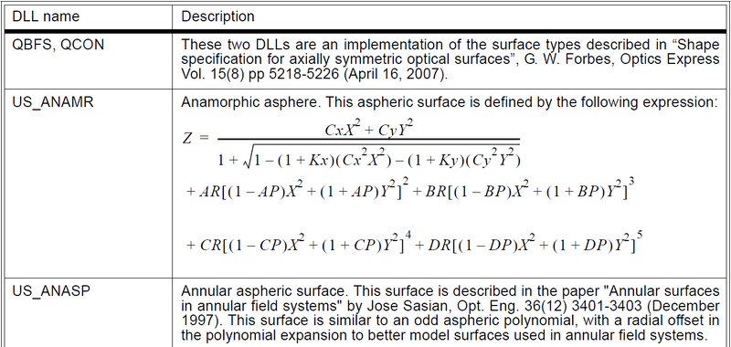
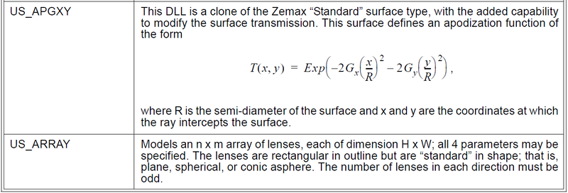
| DLL Name | Description |
| US_ARRAYEVEN | Models an n x m array of lenses, each of dimensions H x W; all 4 parameters may be specified. The lenses are rectangular in outline but are "even aspheric" in shape; that is, plane, spherical, conic asphere, and radial polynomial asphere. The number of lenses in each direction must be odd. |
| US_CYLAR | Models is vertical array of n cylindrical lenses, each H high. The lenses are cylindrical or conic aspheres in the YZ plane. |
| US_DGCYL | Models a diffraction grating on the cylindrical surface, where the grating lines are equally spaced along the arc of the surface rather than equally spaced along the y coordinate of the tangent plane. The grating lines are parallel to the axis of the cylinder. |
| US_DATASURFACE | This surface utilizes the FIXED_DATA4 structure and the ability to pass values from prior Data surfaces. Upon first load it will read extra data values from prior Data surfaces, indicate how many data values were read in Num Values parameter column and copy those values into the EDE. It does not dynamically update. It is solely for illustrating the access to these values in the DLL. |
| US_EAPERIODIC | This surface is similar to the Even Asphere, with an additional term allowing for a sinusoidal variation of the sag. Such variation may be useful for modeling surface irregularities. The full sag expression for the surface is given by:  Where the parameters c, k, and |
| US_FILT1 |
This surface defines an apodization function of the form  |
| US_FILT2 | This Surface defines an apodization function where the optical density is Dmax from zero to a normalized radial coordinate p1, then linearly goes to D=0 at p2, and D=0 |
| US_FILT3 | This surface defines an apodization function of the form  |
| US_FILT4 |
This surface has an apodization function defined by    Where r is the radial coordinate, R is the aperture radius, and
|
| US_FILT5 |
This surface has an apodization function defined by:    Where na is the numerical aperture of the incoming ray, NA is the user
defined parameter, and |
| US_FILT6 |
This surface has an apodization function defined by:  Where |
| US_FILT7 | This surface apodizes the surface transmission via linear interpolation of values specified on the extra data editor as function of either the radial coordinate on the surface or a function of the angle the ray makes with respect to the local Z axis after refraction from the surface. |
| US_FILT8 | This surface models a soft edged rectangular aperture. The MaxX and MaxY parameters are the X and Y half widths of the rectangular aperture. The Transmission varies smoothly from 1 to 0 over twice the distance defined by the DelX and DelY distances from the aperture boundaries. This function make a convenient "soft-edged" aperture which is useful for optimization of transmission through a rectangular aperture. |
| US_GCYL | Models a cylindrical surface with a gradient index medium. The GRIN medium has concentric cylindrical shells of constant index, and a polynomial GRIN profile centered on the center of curvature. This DLL was intended to model light transversing a fiber perpendicular to the axis of the fiber (though the side) |
| US_GRATE | Models a Standard surface with grating lines parallel to the x axis, equally spaced along y in the tangent plane. This is a clone of the Zemax "Diffraction Grating" Surface; different methods are used to measure the Optical Path Length but will usually not cause a ray trace problem. The purpose is to show how diffractive surfaces are model in Zemax UDS DLLs |
| US_GRIN1 | Models a quadratic GRIN medium. This is a clone of the Zemax "Gradient 1" surface. The purpose is to show how GRIN surfaces are modeled in Zemas UDS DLLs. |
| US_HOLOGRAM_KOGELNIK | This DLL models a volume hologram, also called Volume Bragg Grating, based on the following paper - Kogelnik, H. (1969) Coupled Wave Theory for Thick Hologram Gratings. Bell System Technical Journal, 48, 2909-2947. Its construction system is defined in a way similar to surface types Hologram 1 and Hologram 2. More parameters, such as the hologram's average index, modulation index, and Thickness, are used to calculate the diffraction efficiency. Tolerance parameters, such as Shrinkage and Index shift, are included for manufacturability analysis. See Knowledgebase article Simulating diffraction efficiency of a volume holographic grating using Kogelnik’s method for more details about how to use this DLL. |
| US_IGRIN | An example of a GRIN with dispersion. |
| US_ITERA |
This DLL is a clone of the Zemax "Standard" surface, except it uses "dumb" iteration to find the intercept point rather than a closed form expression. The point of this example is to show how to find the surface intercept point if only the sag expression is known. Most polynomial aspheres require this type of iteration because the ray-surface intercept formulas be determined in closed form. Note: The iteration within this sample DLL is simplistic, and may not be able to handle rays with a very large angle of incidence. When used in a wide angle system, the DLL may fail with the following error message: Error 2. In these cases, a more robust algorithm should be used, such as what is given in US_STAND.DLL. |
| US_LUNE |
Models a Luneburg lens, which is a ball lens where the material is a gradient index varying linearly as a function of the distance to the center of curvature, i.e. 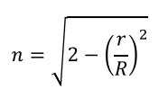 where n is the refractive index, r is the distance to the center of curvature of the ball lens, and R is the radius of the ball lens. |
| US_MEMS |
Models a Micro-Electromechanical System (MEMS), such as a Digital Mirror Device (DMD). The MEMS consists of a 2d array of small rectangular mirrors. The mirrors may tip at any of three angles, each rotated about an axis to point the mirror in any columns, or by individual mirrors if desired to model any state the MEMS can be in. Although the model is strictly geometric, it effectively models where rays are reflected by such a device for an arbitrary setting of the individual mirrors. The parameters on the model are: Nx: Number of X direction mirrors NY: Number of Y direction mirrors Wx: Total width in lens units in X direction Wy: Total width in lens units in Y direction Parameters 5, 6, and 7 (Angle 0, Angle 1, and Angle 2): Angle of mirror in state 0, 1, or 2 Parameter 8 (Rot Angle): Angle of rotation about the Z axis to the tip the mirror Parameter 13 (P Flag): If 0, mirrors are addressed by rows, if 1, by columns, if 2, by individual mirrors. Parameter 14 (Rows 1-15 or Columns 1-15 or Pixels 1-15): State of rows/columns/mirrors 1-15 Parameter 15 (Rows 1-15 or Columns 1-15 or Pixels 1-15): State of rows/columns/mirrors 16-30 Parameter 12+N: State of rows/columns/mirrors 1+15*(N-2)-15*(N-1) The rotation angle effectively rotates the plane of tip of the mirror around the local Z axis; with the initial tip plane being around the local X axis. The rotation angel is measured clockwise from the +y axis. The mirror angles are then tipped about the rotated tip direction. The Parameters are used to define the state of the rows/columns/mirrors using a base 3 integer value. To determine the values for any logic state of the MEMS, construct a table similar to the one below, which shows the values for 3 rows or columns or mirrors: Note the value of the parameter is given by:  Where M1 is the logic state (0,1, or 2) of the first row/column/mirror and M2 is the logic state of the second row/column mirror, ect. Up to 15 row/column/mirror values are defined by each Parameter. |
|
US_MULTI_ZONE_ ASPHERE |
This surface models a series of annular even aspheric zones. Each zone has a radius, conic even asphere coefficients to order 12, and a maximum radial aperture for the zone. Up to 20 concentric zones are supported. Each zone is shifted so the surface is continuous across the zone boundaries. |
| US_OFFST | This offset surface. This surface simulates an additional propagation of distance that is hidden within the surface. This propagation distance is independent for each wavelength. This allows modeling of system that have independent focusing of each color channel such as a digital projector |
| US_OGIVE |
Ogive surface shape. An ogive is a identical to the Standard surface, expect the axis of rotation of the surface is offset by amount ro. The surface sag is given by  Where  |
| US_POLARIZATION | The two DLLs show how to define the electric field or coating. The difference is US_POLARIZATION is based on data structure FIXED_DATA2 and electric field data are exchanged by member double dbreserved[]. And US_POLARIZATION2 is based on data structure FIXED_DATA5 and the electric field data are exchanged by members double Exr, Exi, Eyr, Eyi, Ezr, Ezi. |
| US_POLARIZATION2 | |
| US_STAND | This DLL is clone of the Zemax "Standard" surface type. This is the simplest DLL surface and is a good place to start the study of UDS DLL’s |
| US_STAND2 | This DLL is a clone of the Zemax "Standard surface type using the UserDefinedSurface2 function and structure definition |
| US_ZERNIKE+MSF |
Models a Zernike Standard Sag surface with an additional ripple term described as below. The even aspheric part of the surface sag is defined as 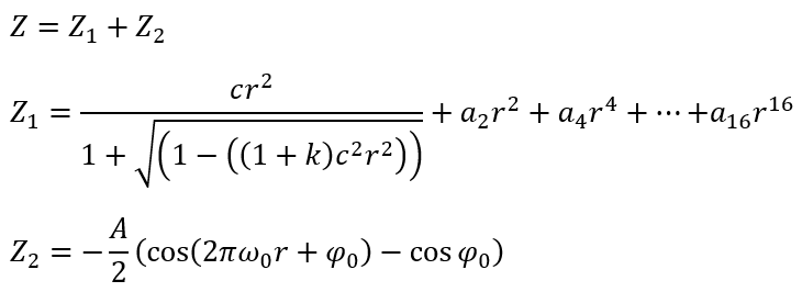 The terms a2, a4 ... a16 have units of length to the power of -1, -3 ... -15. The term A has units of length. The term ω0 has units of inverse length. The term φ0 has units of degrees as entered, but is converted to radians for evaluation in the expression above. See the Knowledgebase article Constructing mid-spatial frequency tooling errors for evaluation and tolerancing for more details about how to use this DLL. |
| Lumerical-metalens-xxxxxx | This DLL models metalens components. To use this DLL, users must first simulate and generate metalens data from Lumerical and then read the data into this DLL. The input are either a pair of files with extension file name .pmap and .aph or a single file with extension file name .h5. The input file should be located in the folder \Document\Zemax\DLL\Surfaces\. To load the input files, we simply need to type the file name in the Comment of the User Defined surface. If the input is the pair of files (.pmap and .aph), it's only needed to type the file name in the Comment column. See Application Gallery article Large-Scale Metalens – Ray Propagation for more guidance about the Metalens workflow. |


| r/c/m: | 3 | 2 | 1 | Parameters |
| 0 | 0 | 0 | 0 | |
| 0 | 0 | 1 | 1 | |
| 0 | 0 | 2 | 2 | |
| 0 | 1 | 0 | 3 | |
| 0 | 1 | 1 | 4 | |
| 0 | 1 | 2 | 5 | |
| 0 | 2 | 0 | 6 | |
| Etc... |
Compile example
To compile a DLL for user-defined code, see the Knowledgebase article How to compile a User-Defined DLL. There is also an example project based on Visual Studio C++ located in {Zemax}\DLL\Surfaces\Solution\AllProjects\.
Next: