


Tolerance Wizard

The default tolerances may be defined by selecting the Tolerance Wizard.
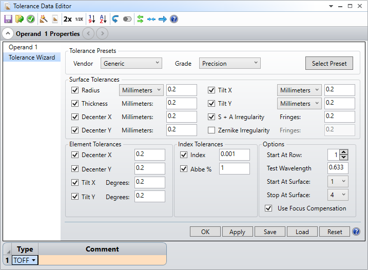
The default tolerances dialog box consists of several sections grouped by tolerance type.
Tolerance Presets
Vendor Lists the available vendors.
Grade Lists the available manufacturing grades, i.e. Commercial, Precision, and High Precision. The Generic vendor also includes a Cell Phone Lens option. The Cell Phone Lens option is based off of default values provided by industry experts.
Select Preset Populates the Surface and Index Tolerances with the settings form the selected Tolerance Preset Vendor and Grade.
(Note: Most Tolerance Presets do not contain Element Tolerances. Please enter those values manually, if assembly tolerances need to be accounted for during the tolerance analysis.)
Surface Tolerances
Radius: If this box is checked, then the default radius tolerances will be included. The default tolerances may be specified by a fixed distance in lens units, a percentage of the nominal radius or by fringes of power at the test wavelength (defined by the TWAV operand). This tolerance is only placed on surfaces which have optical power, which excludes dummy surfaces which have the same index on both sides. If the surface is plano, then the default tolerance is specified as a variation in fringes, even if another option is selected.
Thickness: If checked, a thickness tolerance is specified on each vertex separation. It is assumed that all variations in thickness affect only that surface and any surfaces in contact with that element; therefore, the first air space after the thickness is used as an adjuster. See the detailed discussion in "TTHI: Tolerance on thickness".
Decenter X/Y: If checked, decenter tolerances are added to each individual lens surface. Tolerances are defined as a fixed decenter amount in lens units. OpticStudio uses TSDX and TSDY for Standard surface decenters, and TEDX and TEDY for non-Standard surfaces.
Tilt (TIR) X/Y: If checked, a tilt or "total indicator runout" tolerance in either lens units or degrees is added to each lens surface. OpticStudio uses TSTX and TSTY for Standard surface tilts in degrees, TIRX and TIRY for Standard surface total indicator runout (tilt or wedge) in lens units, and TETX and TETY for non-Standard surface tilts in degrees. If lens units are selected, OpticStudio automatically converts the dimension to degrees of tilt if required for the TSTX/TSTY or TETX/TETY operands. The conversion from total indicator runout in lens units to tilt is given by

Where S is the clear semi-diameter or semi-diameter of the surface and Δy is the total indicator runout, with a similar expression for θy.
This expression assumes the angles are relatively small.
Note that a length of total indicator runout in the x direction corresponds to a tilt about the y axis, and a length of total indicator runout in the y direction corresponds to a tilt about the x axis.
S + A Irreg: If checked, a spherical and astigmatism irregularity is specified on each Standard surface type. For details, see "TIRR: Tolerance on surface irregularity".
Zernike Irregularity: If checked, a Zernike irregularity is specified on each Standard surface type. For details, see "TEZI: Tolerance on surface irregularity using the Standard Zernike model" . By default, OpticStudio uses Zernike terms 2 through 45.
Element Tolerances
Decenter X/Y: If checked, decenter tolerances are added to each lens group. Tolerances may be defined as a fixed decenter amount in lens units.
Tilt X/Y: If checked, a tilt tolerance in degrees is added to each lens group and surface. It is important to note that lens groups are by default tipped about the vertex of the first surface in the group. See the section "TETX, TETY, TETZ: Tolerance on element tilts" for information on tipping about some other point.
Index Tolerances
Index: TIND is used to model changes in the index of refraction. The units are change in relative index.
Abbe: TABB is used to model changes in the Abbe number. The units are percentage of the catalog Abbe value.
Other controls
Start At Row: This control indicates where in the Tolerance Data Editor the default tolerances should be placed. If the row number is greater than 1, then the new default tolerances will be appended starting at the specified row number. If the row number is -1, then the tolerances will be appended to the end of the current list.
Test Wavelength: The wavelength, in micrometers, used to measured fringes of power or irregularity.
Use Focus Comp: If checked, then a default compensator of the back focus (the thickness prior to the image surface) will be defined. Using at least one compensator can greatly relax certain tolerances, however whether or not compensators should be used depends upon the specifics of the design. Other compensators may be defined. See the Section "Defining compensators" for more information.
Start / Stop At Surface: These controls define the range of surfaces to apply the default tolerances to. There are also six buttons:
OK: Accept these settings and generate the default tolerances, and closte the Wizard.
Apply: Accept these settings and generate the default tolerances.
Save: Save these settings for future use.
Load: Restore the previously saved settings.
Reset: Restore the settings to the default values.
Help: Invoke the help system.
By default, the Monte Carlo analysis that OpticStudio performs draws random values from a Gaussian "normal" distribution. Once the default tolerances are defined, they are saved with the lens file automatically. If additional surfaces are inserted in the Lens Data Editor, the tolerance surfaces are renumbered automatically.
Next: