


Interferogram
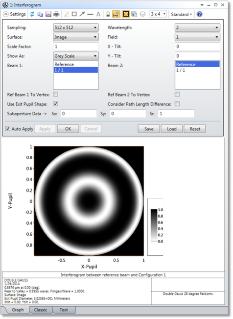
Generates and displays interferograms.
Sampling The size of the ray grid used to sample the pupil. The sampling may be 32x32, 64x64, etc. Although higher sampling yields more accurate data, calculation times increase.
Surface Selects the surface at which the data is to be evaluated. This is useful for evaluating intermediate images. See "Evaluating results at intermediate surfaces" .
Scale Factor Determines the number of fringes per wave of OPD. Useful for modeling double pass interferometers (i.e. use a scale factor of two).
Show As Choose contour map, grey scale, or false color map as the display option.
Wavelength The wavelength is the wavelength number to be used in the calculation.
Field The field number for which the calculation should be performed.
X-Tilt The number of fringes of tilt to add in the x-direction after applying the scale factor.
Y-Tilt The number of fringes of tilt to add in the y-direction after applying the scale factor.
Beam 1 Selects the first beam for the interferogram. See the discussion.
Beam 2 Selects the second beam for the interferogram. See the discussion.
Ref Beam To Vertex Normally, OpticStudio references the OPD to the chief ray; which in effect subtracts out tilt from the wavefront phase. For interferometry, it is sometimes desirable to retain the wavefront tilt. Checking this option on will add tilt to the beam based upon the deviation of the chief ray from the image surface vertex. This option is only useful for field positions whose chief ray is reasonably close to the surface vertex, where the assumption that tilt is described by the deviation of the chief ray is valid. This feature should also only be used when the scale factor is 1.0.
Use Exit Pupil Shape If checked, the shape of the pupil is distorted to show the approximate shape of the exit pupil as seen from the image point for the specified field. The shape is based upon the F/# of the beam in the X and Y pupil directions. If this box is unchecked, then instead the plot will be scaled to circular entrance pupil coordinates, no matter how distorted the exit pupil may actually be.
If Beam 1 is "reference" then the configuration of Beam 2 is used to determine the pupil shape, otherwise the configuration of Beam 1 is used. If both Beam 1 and Beam 2 are defined by different configurations, the shape of Beam 1 is used, and no attempt is made to confirm that the pupils are the same shape. If the pupil shapes are different for the two configurations, this feature cannot accurately predict the interferogram.
Consider Path Length Difference If unchecked, the interferogram is computed assuming the phase at the center of each beam is zero, resulting in a "dark" fringe at the center. No attempt is made to determine the phases of the two beams with respect to each other.
If checked, the difference between the total optical path length of the chief rays in each beam configuration is considered. This setting will alter the phase of the entire interferogram, but will not change the shape of the fringe pattern. For example, if the path difference is exactly one-half wave, dark fringes will become bright and bright will become dark. The optical path length of the chief rays from object to image surface is used, even if the fringes are not localized at the image surface. This assumption is only valid if the fringes are localized on a plane that is the same distance from the image surfaces in each configuration. If a reference beam is selected rather than a beam from a configuration, the optical path length for the reference beam is assumed to be zero.
Contour Format The contour format string. For a discussion of the contour format string syntax, see "The Contour Format String".
Subaperture Data: Sx, Sy, Sr Defines a subaperture of the pupil to compute the interferogram data for. See "Subaperture computations" for details.
Discussion
This feature works by computing two pupil maps, one each from beams 1 and 2. The phase (or OPD) of these two pupil maps is subtracted, and then optionally some linear phase is added as a function of the x and y pupil coordinate to simulate tilt fringes. The individual beams may be OPD as computed for any one configuration, or a "reference" beam which has identically zero OPD may be selected.
Interferometers may be simulated by modeling the two paths through the system using two configurations, and then computing the interferogram of the two resulting beams. The accuracy of this approach is limited by some simplifying assumptions:
- Any lateral shift or magnification difference between the two beams is ignored; it is assumed that the pupils perfectly overlap at the exit pupil.
- Any differences in transmission are ignored; so the two OPD values at any one point in the pupil are assumed to be of equal value in intensity and the phase can be subtracted to yield the net phase difference.
Next: