


Component RBMs
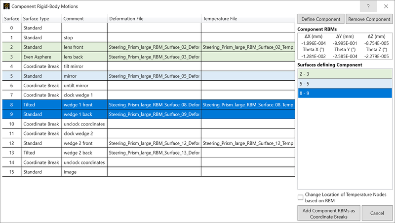
Surface Summary Table Lists all surfaces in the optical design file and the FEA/CFD datasets assigned. Click on surface(s) to define components. Select multiple consecutive items by holding the Shift key while you select.
Define Component Once the surface(s) of the component is selected, click this button to have STAR calculate the average rigid-body motion. A component will be listed in the "Surfaces defining Component"list. Note: Surfaces that are used in a defined component cannot be used to define other components.
Remove Component Remove the component from the Surfaces defining Component list and free up the surfaces to define other components. Note: This option is not available for components that have already had their RBM information converted to coordinate breaks; doing so will cause an error message to appear.
Component RBM Displays the calculated common rigid body motion for the currently defined component.
Surface Defining Component Lists the component(s) defined in the system. Can be used to select and alter a specific component.
Change Location of Temperature Nodes based on RBM Checkbox to control the volumetric datanode adjustment. If the volumetric datafile loaded had the node locations already at the deformed position, this should stay unchecked. If the volumetricdata was supplied with an undeformed mesh, this should be activated to improve alignment. Volumetric datafiles will be transformed to deformed global coordinates based on the component rigid-body motion.
Add Component RBMs as Coordinate Breaks When clicked, STAR will remove the component RBM from the surfaces and add them as Coordinate Breaks around the surface(s). A total of 5 surfaces will be added to the Lens Data Editor (LDE) for each component defined and the Comment of the surface will indicate its function. The surfaces are:
| Surface Type | Comment |
| Coordinate Break | STAR RBM decenters |
| Coordinate Break | STAR RBM tilts |
| Coordinate Break | undo STAR RBM tilts |
| Coordinate Break | undo STAR RBM decenters |
| Standard "Dummy" Surface | original Th to next surface |

Figure 1. Example component surfaces before Component RBMs tool is used.
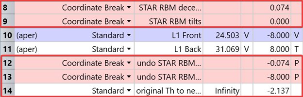
Figure 2. Example component surfaces after Component RBMs tool is used. Note that surface numbers are updated automatically after the Coordinate Breaks are added to the Lens Data Editor.
How to Add Component RBMs as Coordinate breaks
-
In the STAR tab, click Component RBMs. The tool will appear.
-
In the Component Rigid Body Motions tool window, select the surface(s) that comprise a component in your system.
-
Click Define Component. STAR will calculate the average RBMs from the selected surface(s) and display them in the Component RBM table. An entry will appear in the Surface Defining Component list.
-
Repeat steps 2 and 3 for the rest of the components in your system that you want to change to coordinate breaks.
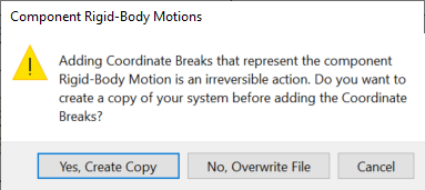
Click the Add Component RBMs as Coordinate Breaks button. STAR will add the coordinate breaks and dummy surface(s) for the components you have defined.
Note: This is a one-way function, there is no undo. It is strongly recommended that you save a new file when prompted by the tool.
Next: