


Winding [Settings]
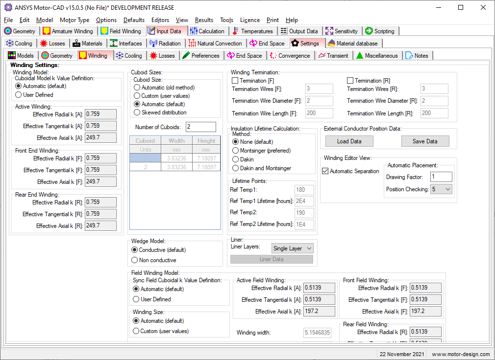
These settings are for the winding thermal model.
There are several different winding settings available here:
Cuboidal Model k Value Definition
Available when the Cuboidal Winding Model is used.
- Automatic - k values are calculated automatically by Motor-CAD.
- User Defined - k values are input by the user.
When this option is set to Automatic the effective k value input boxes (Radial, Tangential and Axial) for the Active Winding, Front End Winding, and Rear End Winding are read-only and show the calculated values.
Cuboid Sizes
This is used to specify the conductor location and level of detail used in the Cuboidal Winding Model.
Wedge Model
How the wedge is treated in the thermal model
- Conductive - the wedge is treated as thermally conductive.
- Non conductive - the wedge is treated as thermally non-conductive.
Winding Termination
See Winding Termination.
Insulation Lifetime Calculation
See Insulation Lifetime Calculation.
Liner Layers
See Liner Layers.
External Conductor Position Data
Winding Conductor positions can be saved or loaded from a separate data file.
Winding Editor View
See Winding Editor View.
Form Wound conductor placement
Only available when the Slot Type is set to Form Wound. Defines the placement of conductors for form wound machines.
- Even spacing - conductors will be spaced evenly in the slot.
- Custom Separation - the conductors will be spaced using the Vertical/Horizontal Conductor Gaps specified in the Winding Definition page.
Sync Rotor Cuboidal Model k Value Definition
Available for the SYNC motor type when the Cuboidal Winding Model is used on the rotor.
- Automatic - k values are calculated automatically by Motor-CAD.
- User Defined - k values are input by the user.
When this option is set to Automatic the effective k value input boxes (Radial, Tangential and Axial) for the Active Field Winding, Front Field Winding, and Rear Field Winding are read-only and show the calculated values.
Winding Size
Available for the SYNC motor type this defines how the rotor cuboids are sized.
- Automatic - the cuboid sizes are calculated automatically by Motor-CAD to fit the winding defined by the user.
- Custom (user values) - the cuboid sizes are input by the user.
When this option is set to Automatic, the Winding width and Winding height input boxes are read-only and show the calculated values.
End Winding Length Adjustment
Available when Hairpin Winding is used as the winding method. The armature end winding length for the front and rear of each layer is calculated automatically based on the winding pattern. This multiplication factor is used to adjust the calculated length to account for any manufacturing effects. Multiplication factors can be chosen for the front and rear of each layer individually. The end winding layer length calculated is shown in the winding output data sheet.
See also: Settings [Input Data Editor]