Through Ventilation Inlet Definition
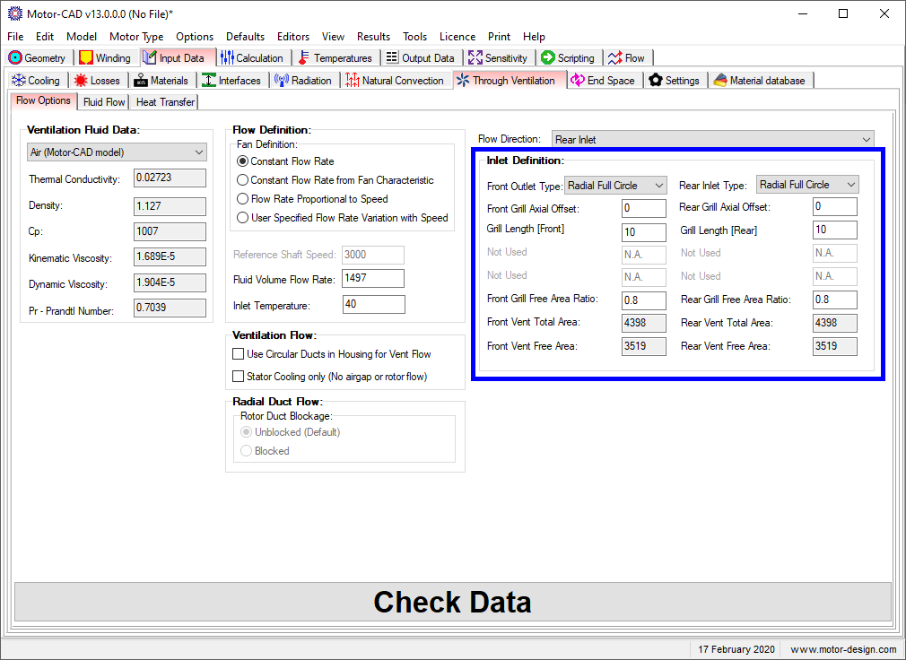
The inlet/outlet vents at the front (drive end) and rear (non drive end) in a Through Ventilation machine can be placed in various positions. The Front Inlet/Outlet Type and Rear Inlet/Outlet Type pull down selectors shown above are used to set where the vents are placed. The options are:
(1) Axial Circular Holes
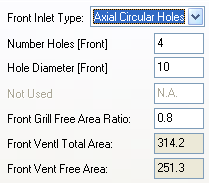
In this case the vents are in the endcap axial surface. The number of vents and the diameter of vents (assumed to be circular vent holes) are set by the Number Holes and Hole Diameter parameters.
(2) Radial Full Circle
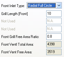
In this case there is a vent in the radial circumference of the motor housing or endcaps that extends for the full circumference of the machine. Only the vent axial length, Grill Length, is required to define the vent area.
(3) Radial Rectangle
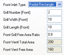
In this case there are a series of rectangular vents in the radial circumference of the motor housing or endcaps.
As with the Radial Full Circle, the vents are in the radial surface of the endcap or housing. But rather than covering the full circumference of the housing they only cover part of it - typically there may be two vents each covering just 1/4 of the periphery. The dimensions of the vents are set using the Grill Number, Grill Length and Grill Widthparameters. The Grill Length is the axial length of each of the vents and the Grill Width the circumferential width.
Front Grill Area
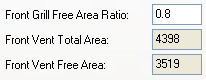
Front Grill Free Area Ratio Sets the ratio of free area for flow to total vent area in a Through Ventilation inlet/outlet vent, i.e. a value of 0.8 means that 80% of a vent is free for air flow while the other 20% is covered by the vent cover (to stop objects entering the machine). (1 = no grill, 0 = blocked grill)
Front Vent Total Area Vent area calculated from the Vent dimensions (ignoring the protection grill).
Front Vent Free Area Free flow area of Vent after taking off the protection grill area.
Rear Grill Area
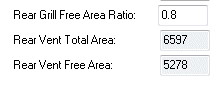
Rear Grill Free Area Ratio Sets the ratio of free area for flow to total vent area in a Through Ventilation inlet/outlet vent, i.e. a value of 0.8 means that 80% of a vent is free for air flow while the other 20% is covered by the vent cover (to stop objects entering the machine). (1 = no grill, 0 = blocked grill)
Rear Vent Total Area Vent area calculated from the Vent dimensions (ignoring the protection grill).
Rear Vent Free Area Free flow area of Vent after taking off the protection grill area.
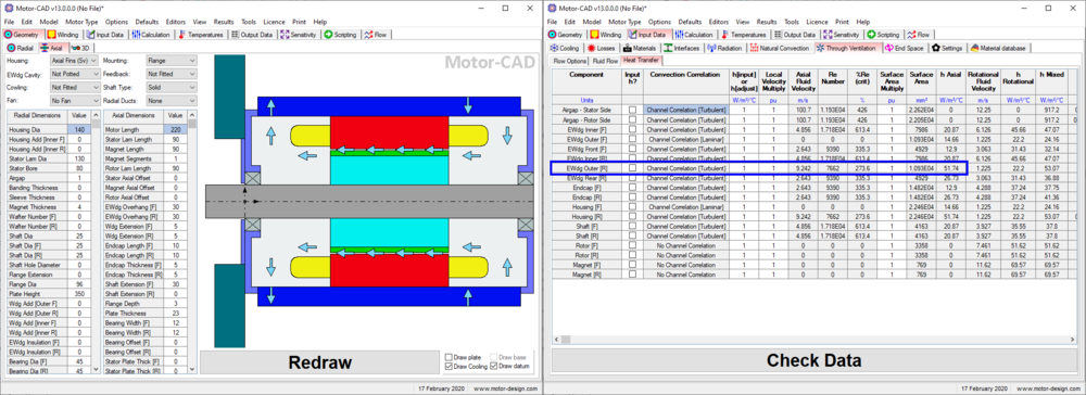
Cooling Flow Path
The chosen inlet/outlet positions (based on the axial offset) affect the cooling circuit. If the vent is positioned above the end winding, axial flow across the end winding outer surface exists, providing increased fluid flow and heat transfer. This can be seen in the Heat Transfer tab, as shown in the image below: