
Network Node and Link Properties
Network node and link properties are defined in dialog boxes, which you can open by double-clicking the component in the schematic.
Face Node Properties
Face node properties are defined in the Edit Face Node dialog box.
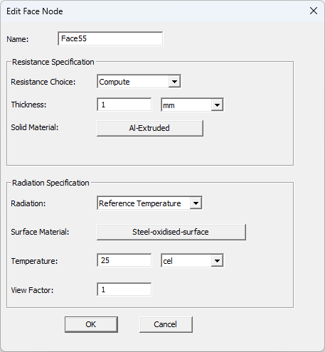
| Resistance Specification | |
| Name | The Name appears in the schematic editor. |
| Resistance Specification | Select Compute or Specified. Compute uses the specified Thickness value and the specified Solid Material thermal conductivity to calculate the thermal resistance. Specified allows you to directly specify the Thermal Resistance value if it is known. |
| Thickness | When Compute is selected, Thickness allows you to specify the thickness of the node. Also specify the Unit of measurement. |
| Solid Material | When Compute is selected, Solid Material allows you to open the Select Definition dialog box to define the node's material. |
| Thermal Resistance | When Specified is selected, Thermal Resistance allows you to directly specify the node's thermal resistance if it is known. |
| Radiation Specification | |
|---|---|
|
Radiation |
Select None, All Objects or Reference Temperature. specifies that the object or surface exchanges radiation with all other objects and surfaces also specified as subject to radiation with heat transfer. Reference temperature specifies a fixed temperature to which the selected sides of the object radiate heat. |
|
Surface Material |
Surface Material specifies the material type for the side of the network using the Select Definition dialog box. |
|
Temperature |
When Reference Temperature is selected, Temperature specifies a fixed temperature to which the selected sides of the object radiate heat. |
|
View Factor |
When Reference Temperature is selected, enter a View factor, which is the proportion of radiation that leaves the network and contacts surrounding objects. The default view factor is 1.0. |
Boundary Node Properties
Boundary node properties are defined in the Edit Boundary Node dialog box.
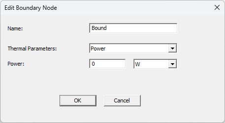
| Parameter Values | |
| Name | The Name appears in the schematic editor. |
| Thermal Parameters | Select Power or Temperature. |
| Power | When Power is selected, specify the power of the node. Also specify the Unit of measurement. |
| Temperature | When Temperature is selected, specify the temperature of the node. Also specify the Unit of measurement. |
Internal Node Properties
Internal node properties are defined in the Edit Internal Node dialog box.
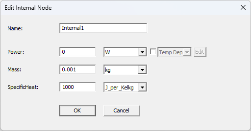
| Parameter Values | |
| Name | The Name appears in the schematic editor. |
| Power | Power allows you to specify the power of the node. Also specify the Unit of measurement. Enable the check box specify temperature-dependent or transient power. For steady-state simulations, if needed, select the check box and select Temp Dep. For Temp Dep, click Edit to specify the temperature dependence of power. For transient simulations, select Temp Dep, Transient, or DTM. Transient allows you to specify power as a function of time. DTM (dynamic thermal modeling) allows you to specify a temperature-dependent power after each time step of a transient simulation. |
| Mass | Mass allows you to specify the mass of the node. Also specify the Unit of measurement. |
| Specific Heat | Specific Heat allows you to specify the heat of the node. Also specify the Unit of measurement. |
- For more information about specifying temperature-dependent power, see Using Datasets to Define Temperature Dependent Parameters.
- For more information on specifying transient parameters, see Specifying Parameters as a Function of Time.
- For more information on dynamic thermal modeling, see DTM - Thermostat for Source Control.
R Link Properties
R link properties are defined in the Edit Link dialog box.
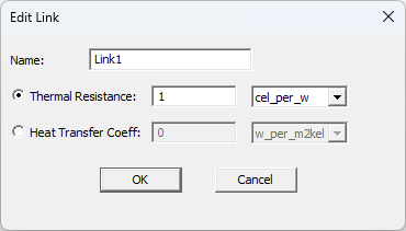
| Parameter Values | |
| Name | The Name appears in the schematic editor. |
| Thermal Resistance | When Thermal Resistance is selected, specify the node's thermal resistance if it is known. |
| Heat Transfer Coeff | When Heat Transfer Coeff is selected, specify the link's convective heat transfer. Icepak computes the thermal resistance as a  , where h is the heat transfer coefficient and a is the area of the face. , where h is the heat transfer coefficient and a is the area of the face. |
MC Link Properties
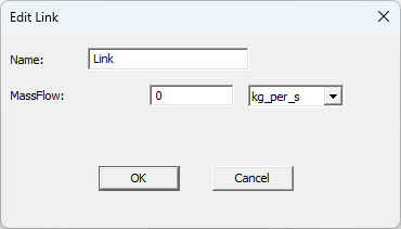
MC link properties are defined in the Edit Link dialog box.
| Parameter Values | |
| Name | The Name appears in the schematic editor. |
| Mass Flow |
Mass Flow allows you to specify the link's mass flow rate. |
Net incoming and outgoing mass flow from MC Links at an internal node should be 0.