How to Assign Thermal Contact
It is important that you read and understand the Contact Guidelines and Examples topic before attempting to assign contact to your model. Doing so will help to ensure that the appropriate object faces are selected and that thermal resistance is correctly defined. The procedure for assigning thermal contact is as follows:
- Select the contact assignment geometry according to one of the following two methods:
- Select one or more faces of solid objects that are touching one or more adjacent solid objects or one or more adjacent shell objects.
- Select one or more shell objects or shell faces that are touching one or more adjacent solid objects. Shell-to-shell thermal contact assignments are not currently supported.
- Select only the primary Contact faces (or shell objects) and not the Target faces. For a fuller explanation, see the guideline concerning contact assignment in the Contact Guidelines and Examples topic.
- You cannot assign contact to the same face to which a convection boundary has been assigned nor to a face that fully or partially overlaps a convection boundary face. An error message will be produced if you attempt to do so. If convection is assigned to an object, that boundary is equivalent to the convection being assigned to all faces of the object. Therefore, that object's faces and any overlapping adjacent object faces are restricted from receiving a contact assignment. The reasons for this restriction are the following:
- Portions of faces that are in contact with other objects are not exposed to the ambient environment and therefore cannot lose heat by convection. Allowing convection at part-to-part interfaces would exaggerate the convective heat flow and skew the temperature and heat flux results.
- A fields summary would report the wrong convective heat flow results at a convection boundary if a portion of that boundary were to be conducting heat directly to another part. Similarly, heat flux and heat flow results would be skewed at areas of overlapping contact and convection.
- Access the Contact dialog box using one of the following three methods:
- In the Project Manager, right-click Contacts and choose Assign > Contact from the shortcut menu.
- Right-click in the Modeler window and choose Assign Contact > Contact.
- From the menu bar, click Mechanical > Contacts > Assign > Contact.
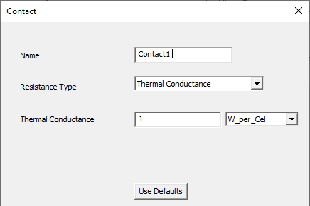
- Optionally, type a new Name to substitute for the default one.
- Choose the desired Resistance Type from the drop-down menu. The choices are as follows:
- Thermal Conductance
- Thermal Conductance per Area
- Thermal Resistance
- Thermal Impedance
- Thickness
- Depending on the resistance type selected in step 4, do one of the following:
- Type in the value of Thermal Conductance, Conductance per Area, Thermal Resistance, or Thermal Impedance and choose the units from the drop-down menu to the right of the text box.
- For the Thickness resistance type:
- Specify the Thickness and choose the unit from the drop-down menu to the right of the text box.
- Click the Material button to access the Select Definition dialog box.
- Choose the material from one of the libraries or define a custom material. Then click OK to close the Select Definition dialog box.
- Click OK to complete the definition and close the Contact dialog box.
Selecting a shell object is equivalent to selecting all of its faces. For a single-face shell, the face and object selection methods produce equivalent contact definitions.
You can use the imprint tool to split the contact portion of a face from the portion to receive a convection boundary, thereby creating two or more separate faces from one original model face.
For more information on each type, see the Thermal Resistance Types topic.
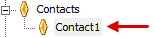
The contact appears in the Project Manager: