
Thermal Contact
Contact with support for thermal resistance is a feature of Mechanical–Thermal solutions in the Ansys Electronics Desktop application. Adjacent parts in electronic assemblies typically have less than perfect thermal contact between them. The roughness of part surfaces reduces the area where the parts are truly touching, and this effect introduces a resistance to the flow of heat between the parts. In order to obtain accurate and realistic temperature results, you must take this thermal contact resistance into account when setting up an analysis model.
Consider a semiconductor device mounted to an aluminum heat sink:
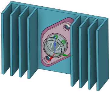
Typically, the greatest temperature gradients occurs at the mounting surface where the semiconductor package and heat sink meet (especially when an electrical insulator is used) and between the heat sink fins and the ambient air. The reason for these greater temperature gradients is that the thermal conductivities within the semiconductor and heat sink are relatively high compared to the conductivity across the part-to-part interface and via convection to the ambient air.
The heat flow through materials, contact faces, and convection boundaries can be represented by a series of resistors (analogous to electrical current flowing from a higher voltage to a lower voltage through a series of resistors). In this case, temperature drives heat flow (in units of power) rather than voltage driving current in amperes. The higher the relative thermal resistance, the greater the temperature change across any of the resistors (in the same way that voltage drop is proportional to resistance in an electrical circuit):
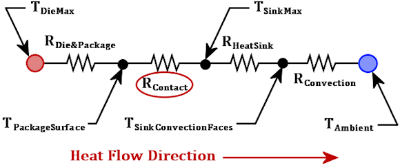
When an insulator is used between the semiconductor and heat sink, RContact can include the combined effective of the insulator's thermal conductivity and thickness as well as the contact resistance on both sides of the insulator. You do not have to include the insulator in the model. Empirical data is available for various standard component packages, insulators, heat transfer enhancement materials (such as silicone grease and thermal pads), and for different clamping forces. Alternatively, you can choose to include the insulator as a solid object in the model and define contact for its front and back faces. In this alternative case, RContact in the preceding diagram would be replaced by three series-resistors representing the semiconductor contact resistance, insulator material conductivity, and heat sink contact resistance, respectively.
The following table shows typical temperatures for a convection-cooled semiconductor and heat sink assembly, as represented by the preceding diagram:
| Location | Temperature (°C) | Corresponding
Resistor |
ΔT (°C) |
| T DieMax | 100 | ||
| T PackageSurface | 94 | RDie&Package | -6 |
| T SinkMax (mounting surface) | 72 | RContact | -12 |
| T SinkConvectionFaces | 68 | RHeatSink | -4 |
| T Ambient (surrounding air) | 25 | RConvection | -43 |
You can consider an increase in thermal contact resistance as a decrease in thermal contact conductance. In fact, resistance is the exact reciprocal of conductance. When defining contact, you can choose to specify either conductance or resistance. Additionally, you can define the conductance or resistance as a total value (for the combined area of the selected faces) or as a distributed value (that is, an area-based value). Additionally, you can specify thermal resistance that is equivalent to a material's thermal conductivity and thickness.