
Results (Structural)
Thermal analysis results presentations fall into two basic categories: Fields Reports and Field Overlays.
- Fields Report:
- Mag_Displacement: Displacement magnitude versus the distance along a specified polyline.
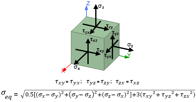
- Equivalent_Stress: The von Mises equivalent stress result (in units of force per unit area) versus the distance along a specified polyline. The von Mises stress combines the effect of six stress tensors into a single positive value. This equivalent stress can be compared directly to a ductile material's yield strength or endurance limit as a predictor of permanent material deformation or fatigue failure. The following diagram and equations show how the equivalent stress is defined in terms of six stress tensors. The diagram shows nine tensors (three tensile/compressive tensors and six shear tensors). However, among the six shear tensors, there are only three unique values. The first of the two equation lines below shows the pairs of shear tensors with identical values. Therefore, the equivalent stress (σeq) equation is based on three tensile/compressive tensor values and three shear tensor values:
- Temperature: Temperature versus the distance along a specified polyline. Temperature results, for Structural solutions, are only applicable to values imported from Icepak (using a non-uniform Thermal Condition excitation).
- Youngs_Modulus_X, Youngs_Modulus_Y, and Youngs_Modulus_Z: (See Note 3.)
- Poisson_Ratio_XY, Poisson_Ratio_YZ, and Poisson_Ratio_XZ: (See Note 3.)
- Thermal_Expansion_X, Thermal_Expansion_Y, and Thermal_Expansion_Z: (See Note 3.)
- Shear_Modulus_X, Shear_Modulus_Y, and Shear_Modulus_Z: (See Note 3.)
- Equivalent_Strain: The von Mises equivalent strain result versus the distance along a specified polyline. This result is dimensionless, though it is often expressed in canceling units of length per unit length. The equivalent strain combines the effect of six strain tensors. Similar to the stress tensors shown in the preceding diagram, there are nine strain tensors—three tensile/compressive tensors (εx, εy, and εz) and six shear tensors. However, as is true for the shear stress tensors, there are also only three unique values for the shear strain tensors (γxy, γyz, and γzx). The following equation shows how the equivalent strain (εeq) is calculated from the six strain tensor values and the effective Poisson's ratio (ν'), which equals the specified Poisson's ratio for isotropic materials undergoing elastic strain:
- Design Volume: The volume of the objects comprising the model.
- Named Expression: A custom result previously defined using the Fields Calculator (see the Fields Calculator Note on the Creating a Report page).
- Field Overlay:
- Mag_Displacement: Color contour overlay of the displacement magnitude.
- Displacement_Vector: Vector overlay of the displacement.
- Equivalent_Stress: Color contour overlay of the von Mises equivalent stress, which is defined in the preceding diagram and σeq equation (under Fields Report).
- Equivalent_Strain: Color contour overlay of the von Mises equivalent strain, which is defined in the preceding εeq equation (under Fields Report).
- Temperature: Color contour overlay of the temperature distribution. Temperature results, for Structural solutions, are only applicable to values imported from Icepak (using a non-uniform Thermal Condition excitation). Use this overlay to verify that temperatures have been imported and mapped to the geometry correctly.
- Youngs_Modulus_X, Youngs_Modulus_Y, and Youngs_Modulus_Z: (See Note 3.)
- Poisson_Ratio_XY, Poisson_Ratio_YZ, and Poisson_Ratio_XZ: (See Note 3.)
- Thermal_Expansion_X, Thermal_Expansion_Y, and Thermal_Expansion_Z: (See Note 3.)
- Shear_Modulus_X, Shear_Modulus_Y, and Shear_Modulus_Z: (See Note 3.)
- Named Expression: A custom result previously defined using the Fields Calculator (see the Fields Calculator Note on the Creating a Report page).
- Fields Summary:
There are several different display types available for fields reports, including 2D (Rectangular) Plots, 3D Plots, Data Tables, and more. One convenient way to generate a report of thermal field results is to draw a polyline running along the faces and/or through the interior volume of your model. This polyline, which can consist of multiple straight and curved segments, defines a path along which you wish to plot a particular structural result. A polyline is required for all predefined structural field results with the exception of Design Volume.
You can also plot user-defined Named Expressions along a polyline or create named expressions that do not need a polyline for plotting.
Regardless of the display type, the following predefined structural results are available for reporting:
(See Note 1.)
Plotted versus the distance along a specified polyline, Young's Modulus (E) quantifies how much a material resists elongation or compression in the direction it is being strained. It is also referred to as a stress-strain curve, and is essentially linear for isotropic materials operating in the elastic range. The units are force per area, and the value represents the stress required to produce a unit of strain. The higher the Young's Modulus, the stiffer the material.
Plotted versus the distance along a specified polyline, Poisson's Ratio (ν) quantifies how the cross-section of a material sample changes as it is strained in the perpendicular direction, such as the way the cross section of a rubber band contracts as the band is streched. Three values are available for plotting, each being the negative of the ratio of transverse strain and axial strain (-εtransverse/εaxial) resulting from an applied axial load. Specifically, νxy = -εx/εy, νyz = -εy/εz, and νxz = -εx/εz.
Plotted versus the distance along a specified polyline, the thermal expansion coefficient of a material, indicates how its length changes with temperature. Its units are 1 per unit temperature, but it is often thought of as delta-length per unit length pre unit temperature, where the length units cancel each other.
Plotted versus the distance along a specified polyline, Shear Modulus (G), also know as the modulus of rigidity, is a measure of the rigidity of a material. Specifically, it is the ratio of the shear stress and shear strain. For the isotropic constituent materials (dielectric and conductor properties), the value of G is calculated from the specified Young's Modulus and Poisson's Ratio according to the relationship, G = E / [2 * (1+ν)].

(See Note 1.)
You can overlay fields on selected solid or sheet objects, faces, or polylines. The following five results are available:
(See Notes 1 and 2.)
(See Notes 1 and 2.)
Color contour overlay of the effective Young's Modulus (E) values in the three coordinate axis directions. See the full description of Youngs_Molulus_X, ... in the above Fields Report section.
Color contour overlay of the three effective Poisson's Ratios (ν). See the full description of Poisson_Ratio_XY, ... in the above Fields Report section.
Color contour plot of the thermal expansion coefficients in the three coordinate axis directions.
Color contour overlay of the three effective Shear Modulus (G) values in the three coordinate axis directions. See the full description of Shear_Modulus_X, ... in the above Fields Report section.
Provide a Summary based on resultant fields data at boundaries, objects (volumes or surfaces), faces (from face selections), or along global or relative coordinate system planes. Summary information includes details such as the minimum, maximum, and mean field values, the standard deviation of the results, and the normal direction vector (for surfaces).
(See Notes 1 and 2.)
These reports, overlays, and fields summary are described more fully, along with the instructions for creating them, in the subsections that follow.
- Generally, stress and strain results are averaged among the elements sharing a common node. The averaging is performed for the individual nodal stress and strain tensors before the equivalent stress and strain results are calculated. However, this averaging is not performed across object boundaries. Where two objects meet at coincident faces, the nodes are shared between the two objects, and bonded contact behavior exists. Though a node may be shared by two different objects, the nodal averaging is only performed for each set of elements belonging to a single object. Therefore, the nodal values associated with each object will differ from each other at the shared nodes (one unique nodal value for each contacting object). This behavior is important especially when the two objects have significantly different material properties. For any given amount of displacement or strain, the object with the lower stiffness (that is, Young's modulus) will typically have the lower nodal stress values, and the stiffer material will experience the higher nodal stresses. Averaging, in this case, would result in stresses being underestimated for the stiffer part and overestimated for the softer part.
- The differing stress and strain values along contact faces will be evident in the Fields Summary when maximal or minimal stresses occur at a contact face (as long as the stresses are summarized separately for each object). The differences will also be evident if a field overlay is assigned to only one of two contacting objects and then compared to stresses with the overlay reassigned to the other object.
- Youngs_Modulus, Poisson_Ratio, Thermal_Expansion, and Shear_Modulus results are only applicable to structural designs that include layout components (in which material properties are mapped to dielectric elements to represent the effect of metal traces and vias). In such cases, the properties can vary throughout the volume of the layout component based on the metal fraction mapped to its grid cells, and they can vary by direction, even though the constituent dielectric and conductor materials are isotropic. Therefore, three separate, directional values are available for plotting for each of these properties.
Constituent dielectric and conductor materials must have isotropic properties. Anisotropic materials are not currently supported for layout components in Mechanical.