
Assigning Modal Materials
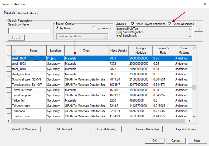
When choosing a material for a modal analysis, you will see a very different set of materials and material properties compared to an electronic circuit or electromagnetics analysis. Instead of properties such as Electrical Conductivity and Relative Permittivity, the physical properties of interest for modal analyses are the material's Young's Modulus, Mass Density, Poisson's Ratio, and Shear Modulus. Only materials with the first three of these four properties defined will appear in the Select Definition dialog box, where you choose the default material or assign an object material.
For isotropic materials, the Shear Modulus (G) is calculated from the Young's Modulus (E) and Poisson's Ratio (ν), according to the following equation:
G = E / [ 2 * (1 + ν) ]
Therefore, the shear modulus is listed as Undefined for the library materials, which are isotropic solids. You can specify shear moduli in three directions for anisotropic solid materials.
Anisotropic Properties
Materials for modal solutions can have simple isotropic properties (that is, behaving quantitatively the same way in every direction), or anisotropic properties (exhibiting different behavior in three orthogonal directions). Specifically, the Young's Modulus, Poisson's Ratio, and Shear Modulus can vary in each of the three orthogonal directions. These directions are defined by the Orientation property of each object that uses the material (indicating a global or user-defined coordinate system).
All predefined library materials are of the simple (isotropic) type. You must define your own custom material to use anisotropic properties.
See the Defining Anisotropic Tensors topic for more information.
Default Material and Applicable Libraries
The default material for modal analyses is steel_1008, which is a standard AISI low-carbon grade of steel. The following libraries contain materials suitable for Modal solutions:
- [sys] GRANTA Materials Data for Simulation
- [sys] GRANTA Producers Materials Data for Simulation
- [sys] Materials
- [sys] Vacuumschmelze
Non-Applicable Materials
Fluid materials are not applicable to modal analyses and are filtered from the libraries. Additionally, Modal solutions do not currently support anisotropic or temperature-dependent material properties.
Material Selection
To set the default material for all objects you subsequently create:
- At the far right end of the Draw ribbon tab, choose Select from the Default material drop-down menu.
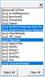
- In the Libraries list, ensure that one or more of the previously listed suitable libraries are selected, or a user library with mechanical material properties. Click the ellipsis button ( ... ) to the right of the Libraries list to access a pop-up dialog box in which you can select which libraries to include in the Materials list:
- Optionally, type a portion of the material name in the Search by Name text box. The list will automatically scroll as needed and the first material matching the search string will be selected. If you scroll the selected material off screen, click Search to quickly bring the searched material back into view.
- Select the desired material, if present.
- Optionally, to define your own material properties, click Add Material.
- Optionally, to specify anisotropic properties for the Young's Modulus, Poisson's Ratio, or Shear Modulus (when properties by direction), select Anisotropic from the Type drop-down menu. Otherwise, the Simple option is for isotropic properties (when the properties are the same in every direction).
- If editing properties, or defining a new material, specify the desired Material Name, Mass Density, Young's Modulus, and Poisson's Ratio. The following material validation rules apply:
- For simple (isotropic) materials:
- Mass Density (ρ) must be greater than zero: (ρ > 0)
- Young's Modulus (E) must be greater than zero: (E > 0)
- Poisson's Ratio (ν) must be in the range: (-1 < ν < 0.5, non-inclusively)
- For anisotropic materials:
- Mass Density (ρ) must be greater than zero: (ρ > 0)
- Young's Modulus (E) must be greater than zero in all three directions: [for E, T(1,1) > 0, T(2,2) > 0, and T(3,3) > 0]
- Shear Modulus (G) must be greater than zero in all three directions: [for G, T(1,2) > 0, T(1,3) > 0, and T(2,3) > 0]
- Material must be positive definite as defined by the following function of Young's Modulus (E) and Poisson's Ratio (ν):
- Optionally, select the Use Material Appearance option and specify the desired Color and Transparency attributes.
- Optionally, click Validate Material to check for errors in the specified properties.
- Click OK to close the View / Edit Material dialog box.
- Click OK to close the Select Definition dialog box.
The Select Definition dialog box appears.
Alternatively, select the Select all libraries option:
This option is selected by default for new projects.
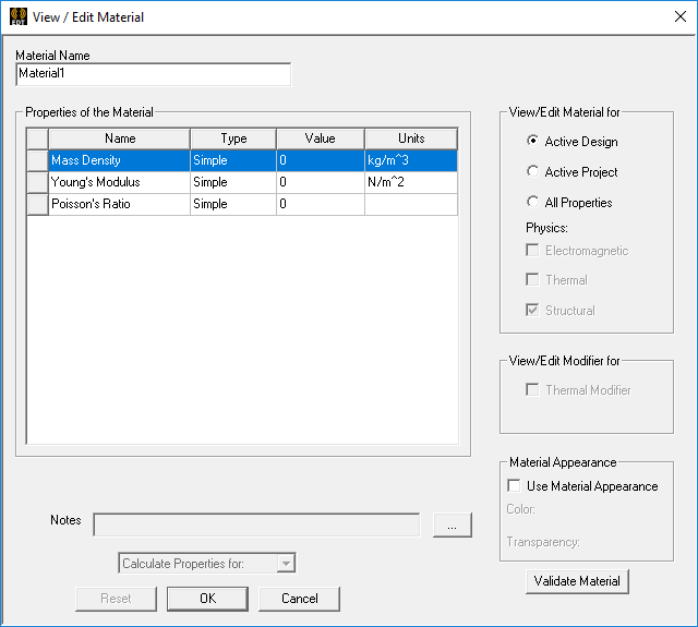
The View / Edit Material dialog box appears:
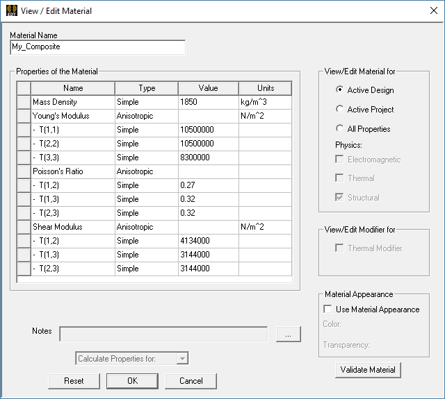
For Young's Modulus, T(1,1), T(2,2) and T(3,3) respectively correspond to Ex, Ey, and Ez (the moduli in the three axis directions, whether the coordinate system is global or user-defined).
For Shear Modulus, T(1,2), T(1,3) and T(2,3) respectively correspond to Gxy, Gxz, and Gyz (the moduli based on the three axis directions, whether the coordinate system is global or user-defined).
(1 - ν122 * E2/E1 - ν232 * E3/E2 - 2 * ν12 * ν23 * ν13 * E3/E1) > 0
For Poisson's Ratio, T(1,2), T(1,3) and T(2,3) respectively correspond to νxy, νxz, and νyz (the ratios based on the three axis directions, whether the coordinate system is global or user-defined).
The following is an example of the properties for an anisotropic material:
If the properties pass the validation check, a green check mark appears to the right of the Validate Material button. Otherwise, a red X appears, and a pop-up message provides the error details.
To assign a different material to a selected solid object:
- Select the object to which you want to assign a material.
- Use one of the following five methods of accessing the Select Definition dialog box:
- On the Draw ribbon tab, click
 Material.
 - Using the menu bar, click Modeler > Assign Material.
- Right-click in the Modeler window and choose Assign Material from the shortcut menu.
- In the Attribute tab of the docked Properties window, choose Edit from the Material Value drop-down menu.
- If the Properties dialog box appears automatically when you create an object, select the Attribute tab. Then, choose Edit from the Material Value drop-down menu.
- Complete steps 2 through 6 of the previous procedure.
To add, remove, or edit materials:
- Use one of the following two methods of accessing the Edit Libraries dialog box:
- Using the menu bar, click Tools > Edit Libraries > Materials.
- Under Definitions in the Project Manager, right-click Materials and choose Edit Library from the shortcut menu.
- Select the desired material library from the Libraries list, or select Show all libraries.
- Select an existing material or click Add Material to define a new one.
- Optionally, you can click the following buttons once you've selected one or more existing materials:
- View / Edit Materials: To change the name or properties.
- Clone Material(s): Make copies of the selected materials as a starting point for defining new ones.
- Remove Material(s): Remove the selected materials from the library.
- After making the desired changes, click OK to close the View / Edit Material and/or Edit Library dialog boxes.
When you change the properties of a SysLibrary material, a new Project library material is created.
You cannot remove predefined SysLibrary materials. You can only delete materials that you've added to a the project library or a user library (and only if the material is not being used in the current design).